5th USENIX Conference on File and Storage Technologies - Paper
Pp. 261–276 of the Proceedings
REO: A Generic RAID Engine and Optimizer
Deepak Kenchammana-Hosekote*, Dingshan Hef , James Lee Hafner*
*IBM Almaden Research Center, f Microsoft
Abstract
Present day applications that require reliable data storage use one
of five commonly available RAID levels to protect against data loss
due to media or disk failures. With a marked rise in the quantity of
stored data and no commensurate improvement in disk reliability, a
greater variety is becoming necessary to contain costs. Adding new
RAID codes to an implementation becomes cost prohibitive since they
require significant development, testing and tuning efforts. We
suggest a novel solution to this problem: a generic RAID
Engine and Optimizer (REO). It is generic in that
it works for any XOR-based erasure (RAID) code and under any
combination of sector or disk failures. REO can systematically
deduce a least cost reconstruction strategy for a read to lost pages
or for an update strategy for a flush of dirty pages. Using trace
driven simulations we show that REO can automatically tune I/O
performance to be competitive with existing RAID implementations.
1 Introduction
Until recently, protecting customer data from loss due to media
failure and/or device failures meant storing it using one of five RAID
levels [32]. To handle higher performance and
reliability needs of customers, storage vendors have deployed
hierarchical codes like RAID 51. These codes are offered as a result
of juggling the inherent risk-reward trade-off from a software
engineering standpoint and not out of any merits, whether in storage
efficiency or performance. Since these codes can be composed by
re-using e.g., hierarchically, the basic RAID set, source code added
was minimal. This meant that product marketing needs could be
satisfied with low test expense.
There were good reasons why only a few RAID codes were supported in
traditional RAID controller implementations (firmware). Firmware
complexity grows with every supported RAID code, increasing
development and test costs. When firmware becomes a large collection
of specific cases it becomes hard to do path length optimizations.
From a software maintainability standpoint, a collection of
if... then... else... code blocks makes firmware
readability harder and more prone to bugs. Each roll out of a RAID
code potentially requires field upgrades.
Since deploying firmware changes is painful there is a general mindset
to avoid it at all costs. However, recent trends in storage technology
and customer focus are forcing a re-evaluation. First, no single RAID
code satisfies all aspects of data storage. Supporting a variety of
RAID codes becomes valuable for effective information lifecyle
management where data should be stored at performance, reliability and
efficiency levels that are proportionate to its business value.
Second, the nature of reference data is that while the dataset grows
from gigabytes to petabytes its reliability must remain relatively
constant. Using the same RAID code for all sizes is not practical
since disk failures grow with capacity[8,36]. A
third reason is the growing popularity of modular systems where
bricks [17] are the building blocks to systems that
scale in capacity and
performance [36,31,2,37]. Some of these
systems [11] even simplify management using fail-in-place
strategies. Another trend is to use low cost serial ATA (SATA) disks
in building large systems [26]. SATA disks have hard
error rates that are 10x higher than comparable SCSI
disks [10,18] while being 30-50% cheaper.
Providing high data reliability using less reliable disks requires a
greater variety of RAID codes.
In light of the tension to provide a variety of RAID codes without
compromising the quality, performance, and maintainability of the
firmware, we can draw up a list of requirements for an ideal solution:
(1) It should allow for adding new RAID codes without firmware
complexity, (2) It should easily support popular RAID codes e.g.,
XOR-based ones which can be implemented efficiently in hardware and/or
software, (3) It should automatically handles any RAID code related
error handling e.g., read error to a failed sector or disk, (4) Since
error handling constitutes a large fraction of any RAID
implementation, ideally, the solution should fold fault-free and
fault-ridden cases into common code paths. (4) It should simplify
nested error paths e.g., in the process of reconstructing a lost block
due to a previous failure, a new sector or disk failure is discovered.
While the successful completion can occur only if the RAID code
permits, an ideal solution must figure out automatically how to do
reconstructions. (5) It should automatically tune I/O performance by
leveraging dynamic state e.g., cached pages. (6) It should offer
informal arguments for correctness, if not formally provable.
Our contributions
We present our efforts at building a generic RAID Engine and Optimizer
(REO) fits the above requirements. It is generic in that it works for
any XOR-based erasure (RAID) codes (including N-way mirroring) and
under any combination of sector or disk failures. In a typical
deployment REO routines are invoked by the block data cache in the I/O
stack to read, write, scrub, rebuild, or migrate data stored on disks
using RAID codes. REO can systematically deduce reconstruction and
update strategies and execute them. In addition, an online optimizer
within REO can select a least cost strategy for every read or write
based on the current cache content. This optimizer can be configured
to minimize any system level objective e.g., disk I/O or memory bus
usage. By parameterizing fault state, REO can eliminate myriads of
cases including those involving nested recovery into a single code
path. Finally, by building on results that have been formally proved,
we can informally argue about the correctness of REO.
This paper is structured into a high level overview of REO
(Section 3) followed by detailed description
(Sections 4- 6). While
these sections focus on read and write operations,
Section 7 discusses scrub, rebuild, and migrate. An
evaluation of the efficacy of optimization is discussed in
Section 8. Some adaptations to future trends in I/O
architecture are presented in Section 9.
2 Related work
There has been no dearth of RAID codes proposed until now e.g.,
EVENODD[3], generalized
EVENODD [4], X-code [42],
RDP [12], WEAVER [19]. Recently, there have been
a few non-XOR code implementations [8,33]
but these have remained niches since they offer no special advantage
over the simplicity of XOR based codes.
One past effort that has focused on providing firmware environments
that permit rapid prototyping and evaluation of redundant disk array
architectures was RAIDframe[14]. It modularized the basic
functions that differentiate RAID architectures - mapping, encoding
and caching. Such a decomposition allowed each aspect to be modified
independently creating new designs. Array operations were modeled as
directed acyclic graphs (DAGs), which specified the architectural
dependencies (and execution) between primitives. While it allowed a
structure to specify exception handling, RAIDframe lacked any ability
to automatically tune performance.
Recently, RAID system-on-chip (SOC)
products [27], [6] and [25] have become
available. The Aristos SOC, which exemplifies this category, contains
an embedded processor, DMA/XOR engines and host and disk interface
logic. Since the processor is programmable it is conceivable that they
could support a variety of RAID codes. However, the problem with it is
that all error paths must be specified as callbacks (much like
RAIDframe) which must be written by the developer. Further, it is
unclear to us how automated (if at all) the performance tuning is.
3 Overview
REO is a set of routines invoked by a (block or file) data cache when
reading or writing data to a RAID coded volume e.g., RAID 1, RAID 5,
EVENODD, etc., as shown in Figure 1. In it,
applications generate read and write requests to the I/O subsystem
that are serviced by a data cache. With write-back caching,
application writes are copied to pages in the data cache and marked
dirty. At a later time, as determined by the page replacement policy,
dirty pages are flushed (written out) to disks. With read caching,
when possible, application reads are served out of the data cache. On
a read miss, the cache first fetches the data from the disk(s) and
then, returns it to the application. Most data caches dynamically
partition write-back and read pages to handle a variety of application
workloads. In many RAID controllers and filers [23] the
write-back cache is protected from unexpected power failure.
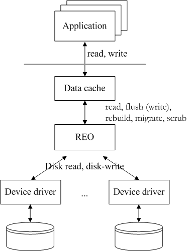 Figure 1: Figure shows a typical deployment of REO within the I/O
stack. One or more applications generate read or write calls to
RAID coded volumes. These requests are first attempted to be
served by the block data cache. If a read miss occurs or a page
needs to be flushed then, REO routines are invoked. REO routines
include RAID housekeeping functions like rebuild, migrate and
scrub. These routines can support any RAID code, under any set of
sector or disk failures while simultaneously considering the
current cache state.
Figure 1: Figure shows a typical deployment of REO within the I/O
stack. One or more applications generate read or write calls to
RAID coded volumes. These requests are first attempted to be
served by the block data cache. If a read miss occurs or a page
needs to be flushed then, REO routines are invoked. REO routines
include RAID housekeeping functions like rebuild, migrate and
scrub. These routines can support any RAID code, under any set of
sector or disk failures while simultaneously considering the
current cache state.
3.1 Use cases for REO
REO routines are invoked by the data cache in four scenarios:
- Read on a miss (reo_read): The virtualized block
address of the requested page(s) is translated to its physical
block address within the identified disk. In the fault-free case,
disk read(s) is issued. If that disk (or particular sectors within
it) has failed then, a reconstruction must be done by REO by reading
related blocks according to the RAID code. Sometimes, reconstruction
is impossible in which case a read error is returned.
- Flush a dirty page (reo_write): When the cache
replacement policy has picked a victim (dirty) page to be written to
the disk, the virtual block address of the victim is translated to
its physical block address within the identified disk. REO must
identify the dependent parity block(s) from the RAID code
information and figure out how to update them. This use case covers
write-through writes e.g., when write-back caching is disabled.
- Rebuild a lost page (reo_rebuild): Generated by an
internal housekeeping routine to repair lost data (due to sector or
disk failure), REO must first reconstruct the lost page using the
redundant information within the RAID code and then, write it to a
new location. Rebuild can be viewed as a composite operation -
reconstruct read followed by write.
- Migrate a page (reo_migrate): Triggered by an
administrative action, migration is invoked to change the RAID code
of a set of pages. Migration includes varying the span (rank) of
disks (8-disk RAID 5 to 5-disk RAID 5) and changing the RAID code
(RAID 5 to EVENODD). Like rebuild, migration can be viewed as a
composition - read, using the old code, followed by write, using
the new code.
Since rebuild and migrate are compositions, we focus primarily on
describing reo_read and reo_write operations. We
defer discussing reo_rebuild and reo_migrate to
Section 7.
3.2 Two components of REO
REO routines can be functionally partitioned into two components: a
RAID Engine which figures out what is to be done, and an
Execution Engine which figures out how it gets done.
Figure 2 sketches this breakdown. The RAID engine
transforms the input arguments into an I/O plan which comprises a set
of blocks to be read, a set to be XOR-ed, and a set to be written.
Such an I/O plan is input to the execution engine which issues the
necessary disk reads and writes and XOR operations.
 Figure 2: Figure shows a component breakdown of REO into a RAID
Engine and Execution Engine. The RAID Engine takes inputs to
compute an I/O plan. All its inputs are readily available within
the meta-data, system data structures and/or cache directory. An
I/O plan includes a set of pages that must be read from the disks,
a set of pages that must be XOR-ed, and a set of pages that must
be written. Depending on the inputs some of these sets may be
empty. The Execution Engine detects and handles error handling
during the execution of an I/O plan. If it encounters any errors
then, it aborts the I/O plan, modifies the fault configuration
vector, and re-submits the operation to the RAID Engine. An online
Optimizer within the RAID Engine selects strategies that suit a
configured system level objective.
In addition to the basic operation type (reo_read or
reo_write) and their arguments - the page(s) block
address, starting virtual block address, and number of bytes to be
read or written - the RAID Engine requires the following inputs to
generate the I/O plan:
Figure 2: Figure shows a component breakdown of REO into a RAID
Engine and Execution Engine. The RAID Engine takes inputs to
compute an I/O plan. All its inputs are readily available within
the meta-data, system data structures and/or cache directory. An
I/O plan includes a set of pages that must be read from the disks,
a set of pages that must be XOR-ed, and a set of pages that must
be written. Depending on the inputs some of these sets may be
empty. The Execution Engine detects and handles error handling
during the execution of an I/O plan. If it encounters any errors
then, it aborts the I/O plan, modifies the fault configuration
vector, and re-submits the operation to the RAID Engine. An online
Optimizer within the RAID Engine selects strategies that suit a
configured system level objective.
In addition to the basic operation type (reo_read or
reo_write) and their arguments - the page(s) block
address, starting virtual block address, and number of bytes to be
read or written - the RAID Engine requires the following inputs to
generate the I/O plan:
- A concise description of the RAID code, available from the
meta-data.
- A description of the physical arrangement of blocks in the RAID
code called the layout, available from the meta-data.
- A description of known sector or disk failures called the fault
configuration, available from system managed data structures.
- A list of clean and dirty pages presently in the data cache
surronding the page(s) to be read or written, available from the
data cache directory.
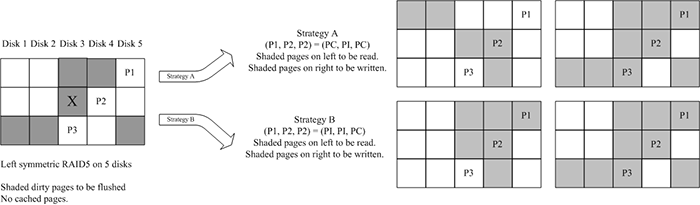 Figure 3: Figure illustrating two (of a total of eight) strategies
possible while flushing a set of dirty pages for a 5-disk
left-symmetric RAID 5 coded volume. On the left, the shaded pages
show the dirty pages that are within a single stripe neighborhood
of a victim page marked"X". On the right, we show the resulting
pages that would have to be read and written if one strategy were
chosen over the other.
A final input to the RAID Engine is a resource optimization objective.
This can include (but not limited to) criteria like minimizing disk
I/O or minimizing memory bus bandwidth. This input guides the
Optimizer, a component within the RAID Engine, whenever it has a
choice of strategies for any read or write.
The Optimizer has little variety for fault-free reads where the only
reasonable option is to read the required page directly from the
appropriate disk. For writes there can be more choices. Each choice
can require a different number of disk reads and/or XOR operations. In
such cases, the configured objective function is used by the optimizer
to guide selection.
Before starting on an I/O plan, the Execution Engine acquires all
necessary page and stripe locks. Then, it carries out the plan in
three phases: first, it submits the disk reads (if any); next, it
performs the XOR operations (if any); finally, it submits the disk
writes (if any). During any of these steps, if it encounters failed
sectors or disks, it re-submits the entire operation to the RAID
Engine along with the newly discovered fault state. In
Figure 2 shows this resubmission step. One
advantage of such a structure is that the recovery code is no
different from the main code path.
Figure 3: Figure illustrating two (of a total of eight) strategies
possible while flushing a set of dirty pages for a 5-disk
left-symmetric RAID 5 coded volume. On the left, the shaded pages
show the dirty pages that are within a single stripe neighborhood
of a victim page marked"X". On the right, we show the resulting
pages that would have to be read and written if one strategy were
chosen over the other.
A final input to the RAID Engine is a resource optimization objective.
This can include (but not limited to) criteria like minimizing disk
I/O or minimizing memory bus bandwidth. This input guides the
Optimizer, a component within the RAID Engine, whenever it has a
choice of strategies for any read or write.
The Optimizer has little variety for fault-free reads where the only
reasonable option is to read the required page directly from the
appropriate disk. For writes there can be more choices. Each choice
can require a different number of disk reads and/or XOR operations. In
such cases, the configured objective function is used by the optimizer
to guide selection.
Before starting on an I/O plan, the Execution Engine acquires all
necessary page and stripe locks. Then, it carries out the plan in
three phases: first, it submits the disk reads (if any); next, it
performs the XOR operations (if any); finally, it submits the disk
writes (if any). During any of these steps, if it encounters failed
sectors or disks, it re-submits the entire operation to the RAID
Engine along with the newly discovered fault state. In
Figure 2 shows this resubmission step. One
advantage of such a structure is that the recovery code is no
different from the main code path.
3.3 Supporting mirrors
One popular RAID code that, at a first glance, appears not to be
XOR-based is RAID 1 and, more generally, N-way mirroring. However,
such codes are technically degenerate cases of XOR-based erasure codes
where each additional copy can be thought of as parity computed from
the primary copy and implicit zero entries for a comparable erasure
code (RAID 1 with RAID 5, 3-way mirror with EVENODD). Our RAID Engine
leverages this to include support for mirrors and striped mirror codes
like RAID 10. Without loss of generality, we assume that RAID codes
have parity elements in the rest of the paper.
3.4 A RAID 5 example
Before describing the construction of reo_read and
reo_write, we work through an example write that illustrates
the choices available and how different I/O plans entail different
costs in terms of disk reads and writes and the number of XORs.
Figure 3 illustrates this example for a
left-symmetric RAID 5 code. In the left figure, say that the dirty
pages within a one stripe neighbourhood of the victim page (marked
"X") are shaded grey and flushed in a single operation. There are wo
strategies possible to perform this operation (shown on right). Each
strategy is illustrated by two sets of shaded pages - read pages on
left and dirty pages on right. Assuming that a RAID controller can
coalesce requests to contiguous blocks on a disk, the approach on the
top labelled "Strategy A" requires 4 reads, 6 writes, and 14 pages
of memory bus usage for XOR, while "Strategy B" requires 3 reads, 6
writes, and the transfer of 15 pages on the memory bus.
Depending on the configured system level objective REO will choose
between these two strategies. Strategy A would be appropriate if
memory bus usage were to be minimized; Strategy B is better for disk
I/O. The two strategies shown in Figure 3 are
from a possible eight.
4 RAID engine
In order to describe the full construction of the RAID Engine we first
discuss each of its inputs in greater detail.
4.1 Inputs
4.1.1 RAID code representation
In XOR-based erasure codes (RAID codes) any redundant bit is a XOR of
a number of data bits. For efficiency, this relationship is applied to
fix-size chunks of bits called elements. An element typically
consists of one or more consecutive pages on disk. Each page
is made up of multiple sectors. An element can have either data or
parity pages but not a mix of the two. A stripe is the set of
data elements and all related parity elements. A parity element in a
stripe is a XOR of some subset of data elements within that stripe. We
say that the parity element depends on those data elements. The number
of elements that comprise a stripe depends both on the number of disks
(called rank) and the coding scheme. For example, the
2-fault tolerant EVENODD code over 5 devices has 10 elements in each
stripe (Figure 4). Within each stripe, e
consecutive elements are arranged contiguously on each storage device
forming a strip. For simplicity, we assume codes that have
uniform sized elements and strips.
The matrix representation of a RAID code is obtained by expressing the
XOR relationships between data elements and parity elements as a
system of equations [28]. The matrix from such
an organization is called its generator matrix, G. It is a N×M binary matrix, where N is the number of data elements in a
stripe and M is the total number of elements in a stripe (data and
parity). A column of G corresponds to data or parity element in
the stripe. A column component of G corresponding to a data element
will usually have a single 1. For a parity element, the corresponding
column component will have multiple 1's, one for each dependent data
element.
 Figure 4: Physical arrangement of a stripe for a 5-disk 2-fault
tolerant EVENODD code. Each strip contains 2 elements. There are 6
data and 4 parity elements in this stripe.
Figure 4: Physical arrangement of a stripe for a 5-disk 2-fault
tolerant EVENODD code. Each strip contains 2 elements. There are 6
data and 4 parity elements in this stripe.
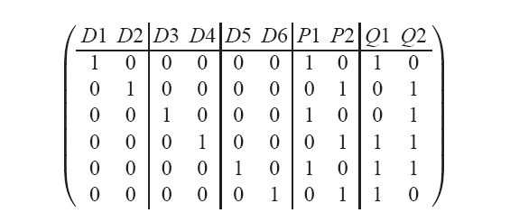 Figure 5: Generator matrix G for a 5-disk 2-fault tolerant EVENODD
corresponding to its physical arrangement. The vertical lines mark
column blocks that correspond to elements within a single strip.
Here, the parity arrangement vector is (7,8,9,10)t.
If each element is k pages then, G can be rewritten in terms of
pages instead of elements by replacing each element entry by an
identity matrix of size k. Without loss of generality and for a
simpler exposition we assume that each element corresponds to a single
page and use the terms elements and pages interchangeably.
Figure 5: Generator matrix G for a 5-disk 2-fault tolerant EVENODD
corresponding to its physical arrangement. The vertical lines mark
column blocks that correspond to elements within a single strip.
Here, the parity arrangement vector is (7,8,9,10)t.
If each element is k pages then, G can be rewritten in terms of
pages instead of elements by replacing each element entry by an
identity matrix of size k. Without loss of generality and for a
simpler exposition we assume that each element corresponds to a single
page and use the terms elements and pages interchangeably.
4.1.2 Layout representation
Layout is the physical (on disk) arrangement of data and parity pages
within a stripe. Besides configuration parameters like the size of
each page, much of the layout can be discerned from the generator
matrix G for the RAID code and e, the number of pages per strip.
As mentioned in the previous section, G can be visualized as blocks
of e columns, each block corresponding to physical arrangement of a
strip on the disk. When parity pages are interspersed with data pages
the layout is interleaved. An example of an RAID code with interleaved
layout is the X-Code proposed by Xu and Bruck [42]
(Figure 8). Examples of codes with non-interleaved
layouts include RAID 5 and EVENODD.
For convenience, it is worthwhile to summarize the location of parity
pages within a stripe in a vector of column indicies corresponding to
parity pages in G. We call this vector the parity arrangement vector
of dimension 1×(M-N).
To allow for even distribution of load across all disks many layouts
are cyclically shifted i.e., columns of the basic codeword are rotated
distributing the parity elements evenly on all disks. This shifting
can be represented by a signed number s that defines the cyclical
shift of strips per stripe. The sign encodes the shift direction -
negative for left-symmetric and positive for right-symmetric. Some
layouts have no cyclical shifting an example of which is the WEAVER
family described in Hafner [19]
(Figure 8).
4.1.3 Fault representation
The failure state of a page can be derived from two sources - failure
state of the disks and the bad sector table. Both kinds of failure
might be either discovered or obtained from system meta-data. We
encode the failure state of a set of n pages as the fault
configuration vector f of dimension 1×n, where an
entry for page i is marked 1 if that page has failed, otherwise 0.
The fault configuration vector gets modified if new errors are
discovered in while executing an I/O plan. This is shown in
Figure 2.
4.1.4 Cache representation
In a write-back cache, the victim (dirty) page is determined by its
replacement policy. While flushing the victim it is efficient to
simultaneously flush dirty pages that belong to the same
stripe [38]. In REO, we extend this idea by
defining a W-neighborhood for a victim page. This is defined as the
set of all pages, clean or dirty, in the data cache that are in a
2W+1 stripe window centered around the victim's stripe. This is
shown in Figure 6. By choosing W > 0, REO can
batch flush requests of multiple pages thereby improving the
throughput of the disks.
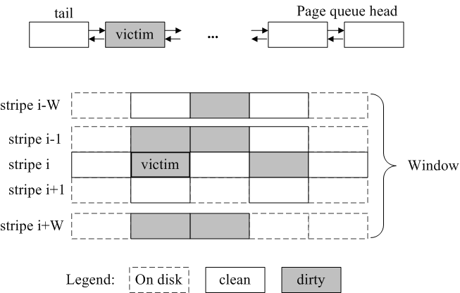 Figure 6: Figure sketches a W-neighborhood of a victim page chosen
by the cache replacement policy based on some page list (shown at
the top). All dirty pages within this 2W+1 stripe window
(centered around the victim's stripe) are written collectively at
a time. Presence of clean pages within the window are leveraged to
reduce I/O or XOR.
The set of pages in the W-neighborhood of a victim page can be
partitioned into clean and dirty page sets. Each set can be encoded as
a binary vector, with a 1 denoting the page in cache. We
denote the two vectors - the clean data vector cv and the
dirty data vector dv.
For write-through operations 0-neighborhood is used.
Figure 6: Figure sketches a W-neighborhood of a victim page chosen
by the cache replacement policy based on some page list (shown at
the top). All dirty pages within this 2W+1 stripe window
(centered around the victim's stripe) are written collectively at
a time. Presence of clean pages within the window are leveraged to
reduce I/O or XOR.
The set of pages in the W-neighborhood of a victim page can be
partitioned into clean and dirty page sets. Each set can be encoded as
a binary vector, with a 1 denoting the page in cache. We
denote the two vectors - the clean data vector cv and the
dirty data vector dv.
For write-through operations 0-neighborhood is used.
4.2 I/O plan output
As Figure 2 shows, an I/O plan is output by the
RAID Engine based on the inputs we have described. Formally, an I/O
plan is a 3-tuple (r,X,w). r is a
binary vector encoding the set of disk read operations necessary; 1
denoting that that page needs to be read. Similarly, w is
a binary vector encoding the set of disk write operations necessary.
X is the set of XOR operations, each of which is a list of pages to
be XOR-ed giving a resultant data or parity page. X can be encoded
as a square matrix of dimension M ×M where a column component
i describes the set of pages to be XOR-ed to compute parity page i.
4.3 REO read
If the pages needed can be read from good disk(s) then, it is trivial
to set r to the corresponding pages on those disk(s). In
this case both X and w are zero.
The challenging case for read is when reconstruction is needed due to
sector or disk failures. To derive a reconstruction strategy we employ
the scheme described by Hafner et al. [7]. For
completeness, we summarize their technique. Starting from the
generator matrix G, a modified matrix [^G] is derived as
follows: for every failed sector, the entries corresponding to that
column in G are zeroed; for every failed disk, the columns
corresponding to pages on disk are zeroed. Formally, [^G] is
computed as follows, [^G] = G (IM -diag(f)), where IM is the identity matrix of
size M and diag(f) is the matrix derived by
applying the fault configuration vector f as the diagonal
of the M×M matrix.
Next, using a variant of Gaussian elimination, a pseudo-inverse R
([^G]-1) is computed. R is of dimension M×N where
the column component i corresponds to a description of the set of
surviving pages (data or parity) that must be read and XOR-ed to
reconstruct data page i.
Two aspects of this scheme, both of which are discussed and proved by
Hafner et al. [7], are central to the RAID
Engine's construction. The first is a result that shows that the
pseudo-inverse technique will always find, if the RAID code permits, a
reconstruction scheme using only the surviving pages (Theorem 1 in
that reference). The second aspect is the non-uniqueness of R. From
linear algebra, since [^G] describes an over-specified system of
equations, its inverse will not be unique. Each pseudo-inverse of
[^G] defines a read strategy. Given a resource optimization
objective, an online optimizer can pick a suitable strategy and its
relevant pseudo-inverse R. Column components of R that correspond
to lost and required pages are extracted to r and X.
Since some of the required pages might already be in cache,
r should be logically AND-ed with the clean cache vector
cv to yield the set of pages that the Execution Engine must
read from disk. Note that in the case of reconstruct reads,
w is zero.
4.4 REO write
4.4.1 Identifying affected parity pages
Recollect that the victim page to be written out is expanded to
include the W-neighborhood of dirty pages. The dirty data vector
dv is the set of pages to be written out including the
victim. In any RAID code the changed content of data pages must be
reflected to its dependent parity pages. Consequently, the first step
is to identify all dependent parity pages. This can be determined by
logically AND-ing the dirty data vector with each column component of
a parity page in [^G]. Every resultant non-zero vector implies
that the surviving parity page must be updated as part of writing
dv. Parity pages with resulting zero column implies either
that the parity page is unaffected or that the parity page cannot be
written because of a sector or disk failure.
In this step we encode the list of affected parity pages as a binary
vector where an entry for a parity page is set to 1 if that page is
affected, 0 otherwise. We denote this as the affected parity vector.
4.4.2 Selecting a write strategy
The next step is to pick how each affected parity page is to be
updated. In RAID 5 any parity element can be updated using one of two
approaches - parity increment (PI) or parity
compute (PC). With PI (a.k.a. read-modify-write), the RAID
controller first reads on-disk versions of the modified data and
parity pages; computes the parity difference between the new and old
version of the data page and applies this increment (delta parity) to
the old parity to compute the new parity. In PC, it reads all
unmodified data pages from disk that a parity page depends on, XORs
them with the dirty pages and computes the parity page.
The problem is how to generalize this for any RAID code under any
fault configuration. To solve this, first we extend the RAID 5
approach to all RAID codes assuming fault-free configurations and
then, we generalize it to allow arbitrary faults.
The extension for a write to a fault-free RAID coded volume is as
follows: Any correct update of dirty pages in a RAID coded stripe is
some combination of parity increment (PI) or parity compute (PC) for
each of the affected parity pages. Note that updates that reuse
results from one parity update (a.k.a. delta parity) for another can
be re-written in a form showing as if each parity page were updated
separately. Each instantiation of a PI or PC for non-zero entries in
the affected parity vector defines a write strategy.
This generalization allows one to systematically enumerate all
possible write strategies. For any write, if p parity pages are
affected then, there will be 2p write strategies. Since each write
strategy translates to a different I/O plan, the optimizer can pick
one that best matches the resource optimization objective.
To handle sector or disk failures the above extension is amended to
allow reconstruction of the pages needed for PI or PC before the
update of the parity page proceeds. Strategy for the necessary
reconstruction(s) is chosen using the approach outlined for
reo_read.
4.4.3 Deriving an I/O plan
Given a write strategy, for each affected parity page, one can compute
the pages to be read, XOR-ed and written independently. REO calculates
the I/O plan by combining the sub-plans for the affected parity pages.
This is done by picking column components from the pseudo-inverse and
translating the write strategy - PI or PC - into the necessary
reads, XORs and writes. The read set is computed mindful of the clean
page vector cv.
If the sub-plan for affected parity page k is denoted by
(rk, Xk, wk) then the combined I/O plan is
derived by summing all the individual sub-plans.
|
r = |
�
k � parity
|
rk; X = |
�
k � parity
|
Xk; w = |
�
k � parity
|
wk |
|
This combined plan is submitted to the Execution Engine.
4.5 An EVENODD example
We work out an example reo_write assuming a fault-free
configuration of the EVENODD code with a rank of 5 disks. The physical
arrangement and generator matrix for this RAID code is shown in
Figure 5. This code has two pages per strip
(e=2), 6 data pages (N=6) and a total of 10 pages per stripe
(M=10) The parity arrangement vector is (7,8,9,10)t.
Let's say that there were two dirty pages - D1 and D3. Then,
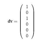 Say there are no clean pages (cv=0) and being
fault-free (f = 0), [^G] = G(IM -diag(f)) = G.
In the first step, the RAID Engine computes the set of affected parity
pages, by AND-ing the dirty page vector with [^G] for each parity
page. Below is a tabulation of this step for each parity page in the
stripe.
Say there are no clean pages (cv=0) and being
fault-free (f = 0), [^G] = G(IM -diag(f)) = G.
In the first step, the RAID Engine computes the set of affected parity
pages, by AND-ing the dirty page vector with [^G] for each parity
page. Below is a tabulation of this step for each parity page in the
stripe.
 Notice that in this write, P2 is unaffected. This is inferred by the
zero column component.
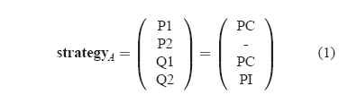
Step 2 is to pick a write strategy. Say, the RAID Engine picks
Notice that in this write, P2 is unaffected. This is inferred by the
zero column component.
Step 2 is to pick a write strategy. Say, the RAID Engine picks
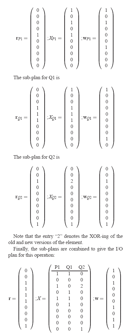 For brevity, only the non-zero columns of X are shown above. The
number atop the horizontal line denotes the column index.
For an example read operation we refer the reader to Section 7 of
Hafner et al. [7].
For brevity, only the non-zero columns of X are shown above. The
number atop the horizontal line denotes the column index.
For an example read operation we refer the reader to Section 7 of
Hafner et al. [7].
5 Optimizer
In the previous section we discussed how the RAID Engine can enumerate
all possible read or write strategies. In this section we discuss the
Optimizer's online selection process. Since each strategy translates
to an I/O plan, the Optimizer drives selection by defining a measure
of goodness for an I/O plan.
5.1 Measures for an I/O plan
For the sake of exposition we describe two plausible measures for a
I/O plan.
- The number of distinct disk read and write commands needed to
execute an I/O plan. Denoted IOC, this metric is intended to measure
disk overhead i.e., total seeks and rotations. In its simplest
version, this measure may weight all seeks and/or rotations equally.
Minimizing IOC leads to lower disk overhead in service requests
which effectively improves the throughput of the disk.
- The number of cache pages input to and output from XOR
operations in executing an I/O plan. Denoted XOR, this measures the
memory overhead incurred. Minimizing XOR leads to lower memory
bandwidth usage.
Note that alternate measures are possible. For example another metric
could use variable seek and rotational costs. Yet another could use a
measure of disk queue lengths. By using IOC and XOR our intent is to
build a framework within which an Optimizer could be built around an
objective function appropriate to the deployment scenario.
5.2 Costing an I/O plan
Given IOC and XOR as plausible metrics, the Optimizer can guide
selection by costing plans from competing strategies. We describe how
the Optimizer can computes these metrics from r, X, and
w.
To compute IOC, both r and w are interpreted as
being blocked. In the resulting vectors, a count of the number of
vertical runs of non-zero entries within each block is IOC since a
vertical run of non-zero entries can be submitted as one sequential
I/O.
To compute XOR, simply sum up all elements in X and the affected
parity vector.
In the example in Section 4.5, IOC = 7 and XOR =
13 for the resultant plan.
If the RAID Engine had chosen the following strategy instead of the
one in Equation 1,
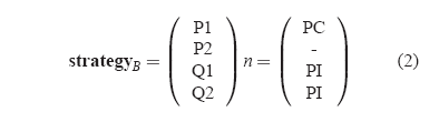 then, IOC = 8 while XOR = 12.
5.3 Selecting strategy
For a given operation, having defined the space of all possible
strategies and some metric for any I/O plan, the Optimizer can employ
any well-known search technique e.g., exhaustive search, dynamic
programming, greedy, randomization, simulated annealing, to find the
least-cost plan. The one constraint in selecting a technique is that
it must be amenable to online computation. Since strategy selection is
done for each I/O that requires doing disk reads and writes, some time
spent selecting is acceptable. However, the time spent searching
should be well worth the resulting savings in disk I/O.
5.3.1 Optimal approach
Technically, it is possible to exhaustively search for the least cost
I/O plan. For reconstruct reads, each distinct pseudo-inverse leads to
a strategy. For each strategy the metric for a resulting I/O plan can
be computed. The number of distinct pseudo-inverses is exponential in
the dimension of its null space and therefore impractical to enumerate
for an implementation. A more practical heuristic is described in
Hafner et. al. [7] which computes
pseudo-inverses that are sparsest which potentially means least IOC or
XOR.
For writes, an exhaustive enumeration of all strategies for a given
operation has exponential complexity w.r.t. the total number of
affected parity pages. For a given operation, the number of affected
parity pages grows if a larger neighborhood is used and/or when higher
fault tolerant RAID code is employed. Since exhaustive search can be
CPU intensive, more practical heuristics are necessary. We describe
two such heuristics - BASELINE and GRADIENT. BASELINE represents
existing RAID implementations. We suggest GRADIENT as an effective
heuristic among a set of search techniques (mentioned earlier) that we
experimented with.
5.3.2 BASELINE heuristic
Most RAID 5 implementations (including Linux
md[40]) employ a simple majority rule to determine
a strategy for a write. If a majority of pages for a stripe are dirty
then, PC is chosen. Else, PI is chosen. Under degraded mode, they
revert to PI. Similarly, for EVENODD and higher distance codes,
thresholding algorithms has been suggested to determine the strategy
for an entire stripe. The thresholding employed to select between PI
and PC for all affected parity elements in the stripe is typically
based on comparing the number of dirty pages within the stripe with a
pre-computed table based on rank etc.
When dealing with failures, structure within the RAID code can be
exploited to minimize recursive reconstructions [21]. The
complexity of this generator is O(p) (p is the number of affected
parity) for RAID 5 and nearly constant for thresholding schemes. In
all implementations we have examined, a window size of 1 is typical
i.e., a 0-neighborhood.
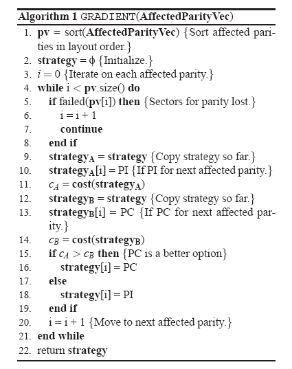
5.3.3 GRADIENT heuristic
The GRADIENT heuristic picks a write strategy by incrementally
assigning PI or PC to each non-zero entry in the affected parity
vector. As each affected parity is assigned the heuristic favors the
assignment that results in a lower cost (based on IOC or XOR).
GRADIENT, outlined in the algorithm below, improves on BASELINE since
a strategy for the next affected parity page is chosen based on the
strategies assigned to previous parity pages. In the algorithm we have
omitted obvious inputs like G, f, cv, dv,
etc. The problem with GRADIENT is that, like any gradient method,
there is no guarantee that it will find the optimal plan. since it
cannot avoid getting stuck in local minimas. While the complexity of
this generator is comparable to BASELINE, it does requires invoking
the costing routine twice for each affected parity page (lines 11
and 14). GRADIENT uses a (static) configured window size. Finding an
efficient heuristic for all layouts under all workloads remains an
open problem.
6 Execution engine
The Execution Engine employs well-known techniques in firmware design
to execute an I/O plan. We summarize its role for clarity and
completeness. As would be needed for higher throughput, multiple I/O
plans will run concurrently within the Execution Engine. Each plan
gets executed in three phases. In Phase 1, any reads are submitted and
completed. In Phase 2, any XORs are calculated. Finally, in Phase 3,
any writes are submitted and completed.
Prior to Phase 1, the Execution Engine re-blocks r and
w just as was done in section 5.2. The
resultant read and write matrices are used by the Execution Engine to
coalesce multiple adjacent disk read/write requests into blocks of
sequential I/Os.
6.1 Handling concurrent plans
The Execution Engine must ensure that all three phases are executed as
part of a single transaction i.e., there is no interleaving of two
concurrently executing IO plans that overlap. RAID controllers must
reads, XORs and writes atomically to satisfy the "atomic parity
update" requirement [38]. If multiple I/O
plans overlap on disk sectors then, the Execution Engine must ensure
that a consistent ordering of data and parity is seen by each
operation. Any robust solution employs one of two techniques -
on-disk log [35] or persistent memory (NVRAM). The
latter approach is commonly employed in commercial RAID controllers
since most do write-back caching which already requires this. In these
implementations, a stripe lock table, kept in persistent memory,
maintains the lock state of stripes being touched by concurrent I/O
plans. The Execution Engine must acquire all locks for stripes in the
W-neighborhood before beginning execution. To avoid deadlocks, all
resources necessary to complete an I/O plan must be acquired in
advance of the plan's execution and in a well-know order.
6.2 Handling failures
During plan execution, various kinds of errors can occur. Errors that
arise out of disk timeout or faulty XOR-ing can be easily retried by
the Execution Engine. Handling errors that arise due to discovering a
new media or disk failure during a plan execution requires a different
tack. In this case, we suggest that the Execution Engine abort the
plan and resubmit the entire operation to the RAID engine with an
updated fault configuration vector. The RAID engine can compute a new
(possibly better) plan that reflects the new fault state. As a side
effect, the Execution Engine could update any fault meta-data managed
by the system.
This step of unifying the error path with the good path in REO is
possible because of the generality with which faults are handled. The
elimination of potentially nested recovery paths contributes to its
simplicity.
7 Other RAID operations
Besides read and write, all RAID controllers must support rebuild.
Rebuild is the operation of reconstructing failed pages within a
stripe and writing them to new disk locations. The rate at which
rebuild is done is a primary determinant of data
availability [15]. In this section we discuss how
reo_rebuild can be made generic to the RAID code.
Most RAID implementations also support RAID migration, a process of
re-laying data that was stored in one layout to another. Migration can
include changing stripe size or its rank (5-disk RAID 5 code to 7-disk
RAID 5 code) or changing the RAID code itself (5-disk 1-fault tolerant
RAID 5 code to 7-disk 2-fault tolerant EVENODD code). We discuss how
REO can be used to support arbitrary RAID migrations.
If stripes have lost more elements from media or disk failure(s) then,
the RAID code can protect against then, none of these operations can
complete successfully. This is due to the inherent limitation of the
RAID code and not of REO.
7.1 REO rebuild
Rebuild occurs when there is a sector or disk failure. In the former
case, rebuild is typically done for the affected stripe which can be
scattered over the volume. In the latter case (disk failure), rebuilds
are batched. Within each batch, multiple stripes are rebuilt
simultaneously since it translates to sequential disk reads and
writes. Keeping a deep queue is essential to speeding up
rebuilds [30]. In both cases, the basic
logic for reo_rebuild remains the same.
A rebuild for a set of lost pages within a stripe is executed in two
steps. In Step 1, reo_read is executed for the set of lost
pages. A read strategy for reconstructing the failed pages is picked
by the RAID Engine and the resultant I/O plan is executed by the
Execution Engine. In Step 2, an I/O plan with w set to the
reconstructed pages is submitted to the execution engine. r
and X for such an I/O plan are zero. Note that the I/O plan in
Step 2 is slightly different from one generated for a similar
reo_write - in some cases, parity pages do not need to be
written during rebuild.
In some implementations the entire stripe is read and written out
instead of just accessing the minimum pages needed for reconstruction.
This is done to detect any lurking sector failures.
reo_rebuild can be suitably modified to reflect this design
decision. Some layouts [29] include spare space for
rebuild within the stripe. Such information can be easily captured in
the layout input to REO.
7.2 REO migrate
In RAID migration, a volume arranged in a source layout is re-arranged
into a target layout. Typically, for space efficiency, this migration
is done in-place i.e., the same set of sectors and disks in the source
layout are reused for the target layout. Migration proceeds in
strides, i.e., multiple stripes. Typically, this multiple is either
determined by the lowest common multiple (LCM) of stride sizes of the
source and target layouts, or by the stride size of the target layout
alone. Sometimes, a staging area on disk is used to store temporary
results if cache memory is limited. In both cases, the basic steps
within reo_migrate are the same.
In a simple version, reo_migrate is executed in 2 steps. In
Step 1, all data pages from the source layout are read using
reo_read. Any reconstructions, if needed, are done in this
step. In Step 2, the list of data pages for the target layout is input
to reo_write as if all the parity pages were lost. Given
this input, a good heuristic will invariably pick PC for all affected
parity elements.
In an alternate implementation of reo_migrate, all pages
(data and parity) in the source layout are read in Step 1. In Step 2,
if possible, parity pages from this layout are reused as partial
results for computing parity pages of the target page. Reusing parity
pages from the source layout has the potential to reduce the memory
bandwidth needed for the migration. However, it has the disadvantage
that errors that have crept in due to bad sectors get propagated to the
target layout.
7.3 Sundry operations
Two other operations commonly implemented are initialization and
scrubbing. Initialization is layout independent in that all regions of
a volume must be zero-ed. This is typically done in batches by writing
sufficiently large writes with zeroes.
Scrubbing is a periodic scan of every stripe to check for latent hard
errors. In REO, scrubbing is implemented by using a parity check
matrix H for a RAID code which is computed from its generator matrix
G. H is a M×(M-N) matrix where each column component
corresponds to a parity page in the RAID code. If all pages with entry
1 in that column are XOR-ed then, the result must be a zero page. A
resultant non-zero page implies an inconsistent parity. H is derived
from G by rearranging column blocks of G into row blocks in H
and including an identity matrix (corresponding to the parity pages).
Figure 7 shows an example parity check
matrix for the 5-disk 2-fault tolerant EVENODD code.
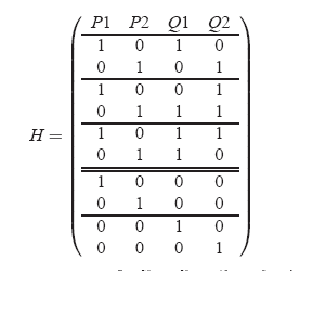 Figure 7: Parity check matrix H for a 5-disk 2-fault tolerant
EVENODD code (Figure 5). H is used to
detect inconsistent pages. H is derived by rearranging column
blocks in G into row blocks and including an identity matrix
that corresponds to the parity pages.
Rectifying stripes that fail parity check is challenging. With higher
fault tolerant codes it is possible to deduce the location of the
error. This is not possible with RAID 5. In some deployments silently
correcting such errors is unacceptable. In cases where it is
acceptable, the parity element is assumed to be wrong and fixed.
Figure 7: Parity check matrix H for a 5-disk 2-fault tolerant
EVENODD code (Figure 5). H is used to
detect inconsistent pages. H is derived by rearranging column
blocks in G into row blocks and including an identity matrix
that corresponds to the parity pages.
Rectifying stripes that fail parity check is challenging. With higher
fault tolerant codes it is possible to deduce the location of the
error. This is not possible with RAID 5. In some deployments silently
correcting such errors is unacceptable. In cases where it is
acceptable, the parity element is assumed to be wrong and fixed.
8 Evaluation
In this section we report results on aspects of REO that are amenable
to quantitative evaluation. We present empirical results from our
experience in adding more than a dozen RAID codes into our simulator.
The efficacy of the Optimizer for real workloads is shown by trace
driven simulations. Other aspects such as correctness can be shown
informally leveraging results proved
elsewhere [7].
8.1 Versatility
| Fault tolerance | Code | Rank | Shift | Strip size | Stripe size (data only) | Storage efficiency | |
| 1 | RAID5 | 8 | -1 | 24 KB | 168 KB | 0.875 |
| 2 | EVENODD2 | 7 | -2 | 24 KB | 168 KB | 0.778 |
| 2 | RDP | 8 | -2 | 24 KB | 144 KB | 0.750 |
| 2 | X-Code | 7 | 0 | 20 KB | 140 KB | 0.714 |
| 3 | EVENODD3 | 8 | -3 | 24 KB | 168 KB | 0.700 |
| 3 | WEAVER3 | 8 | - | 24 KB | 96 KB | 0.500 |
Table 1: RAID codes and their layouts used in our evaluations. These
layouts vary in physical arrangement, efficiency and
performance. EVENODD2 and EVENODD3 are the EVENODD codes for 2 and 3
fault-tolerance respectively. WEAVER3 is the WEAVER code for 3
fault-tolerance. For fairness, we chose layout setting such that the
strip size and rank remained relatively same across RAID codes.
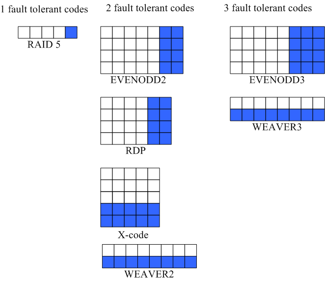 Figure 8: A visual guide to RAID codes studied. Each square
corresponds to an element on a disk. Columns of elements are
physically layed contiguously on a disk. White squares represent
data elements while shaded squares represent parity elements.
Table 1 lists a representative set of RAID codes that we
implemented in a simulator. These codes vary in fault tolerance,
physical arrangement, efficiency, and performance. A visual guide to
stripes of these codes is shows in Figure 8. To
date, we have added more than a dozen RAID codes. Adding a new code
meant specifying its generator matrix and its layout, a task that
averaged about 15 minutes. We believe that this empirical data can be
cautiously extrapolated to real implementations while noting that it
excludes the ensuing system test effort.
Figure 8: A visual guide to RAID codes studied. Each square
corresponds to an element on a disk. Columns of elements are
physically layed contiguously on a disk. White squares represent
data elements while shaded squares represent parity elements.
Table 1 lists a representative set of RAID codes that we
implemented in a simulator. These codes vary in fault tolerance,
physical arrangement, efficiency, and performance. A visual guide to
stripes of these codes is shows in Figure 8. To
date, we have added more than a dozen RAID codes. Adding a new code
meant specifying its generator matrix and its layout, a task that
averaged about 15 minutes. We believe that this empirical data can be
cautiously extrapolated to real implementations while noting that it
excludes the ensuing system test effort.
8.2 Efficacy of Optimizer
Although not central to the value proposition of REO, we have
attempted to quantify the benefits of the Optimizer within the RAID
Engine. For this we built a simulation model that included memory and
I/O buses and integrated it into disksim [13], a
disk simulator with fairly accurate disk and array models. We
simulated the setup shown in Figure 1.
Table 2 lists the fixed parameters for our
experiment and their values. We chose parameters corresponding to a
modest RAID adapter [22].
| Parameter | Setting | |
| Cache size | 128 MB |
| Page size | 4 KB |
| Memory bus bandwidth | 1 GBps |
| I/O bus bandwidth | 500 MBps |
| Disk capacity | 18 GB |
| Disk interconnect BW | 150 MBps |
| Speed | 7200 RPM |
| Single track seek | 1.086 ms |
| Full seek | 12.742 ms |
| Replacement policy | LRU |
| Window size (W) | 0 or 2 |
| Total write ops | 100000 |
Table 2: Parameters used in evaluating the efficacy of
Optimizer. Values were chosen to reflect a modest RAID
controller. Window size was zero for BASELINE
and two for GRADIENT.
To realistically quantify the value of the Optimizer we chose trace
workloads summarized in Table 3. DS1, P5, P13 and
P14 are described by Hsu [20] while TP1, TP2 and SPC1 are
publicly available [39]. Given varying durations and
intensities of these traces we ran our experiments for a fixed number
(100,000) of write I/Os. We did two transformations on the raw traces.
First we time shifted them to begin at t=0. Second, we folded
multiple LUNs in each trace into a single LUN using appropriate block
offsets.
The traces in Table 3 all have a fair amount of
random I/O in them. This was a deliberate choice (over picking
predominantly sequential workloads) in order to make it more
challenging for the Optimizer.
| Name | Description | LUNs | Total Size(GB) | Write(%) | Duration | |
| DS1 | SAP workload | 13 | 46.91 | 90 | 35 mins |
| TP1 | Transaction processing | 24 | 26.01 | 60 | 48 mins |
| TP2 | Transaction processing | 19 | 8.25 | 17 | 1 hr |
| P5 | Workstation file system workload | 2 | 5.54 | 70 | 4 hr |
| P13 | Workstation file system workload | 3 | 3.24 | 57 | 26 hr |
| P14 | Workstation file system workload | 3 | 6.04 | 71 | 10 hr |
| SPC1 | Storage performance council benchmark [39] | 1 | 7.50 | 60 | 56 mins |
Table 3: Traces used in this study. We show statistics for the first
100000 write I/Os of each trace that were used in our
evaluations.
While running a trace, the simulator generated each I/O at the
(relative) time specified in the trace. After 100,000 writes were
generated, the workload was stopped and the remaining dirty pages in
the cache were flushed. The run was deemed complete when there were no
more dirty pages left. At the end of the run we extracted total access
time from each disk in the volume. Access time for a disk request is
the sum of the positioning time (includes seek, rotation, head
switching, and settling times) and transfer time. The total access
time is computed by summing the access times for all disk requests
(read and write). For a given workload, total access time is a good
measure of the total work done by the disks. During each run we
counted the total number of bytes moved on the memory bus. We call
this count the memory bus usage.
GRADIENT's objective was set to minimize IOC over XOR since disks tend
to be the bottleneck. For faults we modeled static configurations
where n disks in a rank were marked as failed for a n failure
configuration prior to starting the trace playback. REO performed all
I/O assuming such a degraded layout.
To factor out sensitivity to system settings and trace specific
patterns, we normalized the total disk access time and the average
memory bandwidths for GRADIENT to those for BASELINE. In
Table 4 we show these normalized values. Total
disk access time and average memory bandwidth are both lower-the-better
measures. This implies that a value below 1.0 means that the optimizer
using GRADIENT "outperformed" BASELINE.
For brevity, we averaged the results from each of the six application
traces (excluding the synthetic benchmark SPC1) for the same layout
and fault configuration. This summary from equally weighted
summarization of the database and filesystem traces is labeled
"Prototypical Workload" in Table 4. The
results for SPC1 trace are shown in separate columns.
8.2.2 Discussion of results
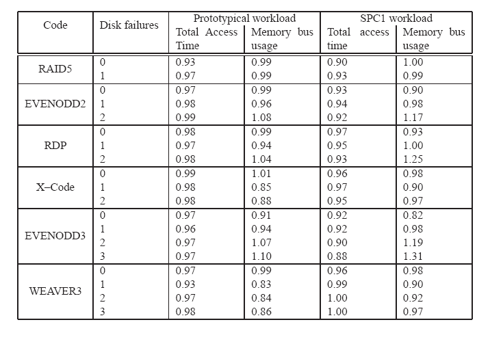 Table 4: Results from trace experiments. All entries in the table
are normalized measures for GRADIENT w.r.t. BASELINE. An entry
lower than 1.0 implies that the optimizer using GRADIENT
"outperformed" BASELINE for that particular setting. Entries under "Prototypical workload"
were obtained by averaging individual results for the three
database and three filesystem traces. Disk failures were
were assumed to be known at start of the run. Notice that, under
some layouts and fault configuration, GRADIENT minimizes total
access times as the expense of memory bus usage. This is
consistent with its resource optimization objective of minimizing
disk I/O. REO with GRADIENT is able to modestly reduce disk I/O at
the expense of increased memory bus usage for common workloads.
Table 4 summarizes the comparison of GRADIENT to
the BASELINE which approximates IBM ServeRAID
adapters[22]. Since GRADIENT was setup to minimize disk
I/Os, we observe that for both workloads, entries in the "Total
access time" columns are less than 1.0, a measure of outperformance
by GRADIENT. Of interest are the entries in the "Memory bus usage"
columns. In some settings e.g., EVENODD3 with 3 faults, the savings in
disk access times comes at the expense of increased memory bus usage.
This occurs because the heuristic favors a strategy that minimizes
IOC over XOR. An example case when this can occur is if, during a
write, PI is chosen for an initial set of affected parity pages
within a window. Even when it might be cheaper from a memory bandwidth
standpoint to choose PC for the subsequent affected parity pages
within the window, the heuristic will favor PI in order to minimize
IOC. This leads to increased memory bus usage at the expense of
reduced disk I/O.
Another reason why GRADIENT outperforms BASELINE on total access times for
RAID 5 layouts is because of a bigger window size. Bigger window sizes
improve the possibility for fewer and larger sequential I/Os.
On average, there was a modest (4-8%) reduction in disk service
times using GRADIENT. The fact that the Optimizer can be competitive
w.r.t. other hand tuned RAID implementations is the more important take
away rather than the magnitude of its outperformance.
Table 4: Results from trace experiments. All entries in the table
are normalized measures for GRADIENT w.r.t. BASELINE. An entry
lower than 1.0 implies that the optimizer using GRADIENT
"outperformed" BASELINE for that particular setting. Entries under "Prototypical workload"
were obtained by averaging individual results for the three
database and three filesystem traces. Disk failures were
were assumed to be known at start of the run. Notice that, under
some layouts and fault configuration, GRADIENT minimizes total
access times as the expense of memory bus usage. This is
consistent with its resource optimization objective of minimizing
disk I/O. REO with GRADIENT is able to modestly reduce disk I/O at
the expense of increased memory bus usage for common workloads.
Table 4 summarizes the comparison of GRADIENT to
the BASELINE which approximates IBM ServeRAID
adapters[22]. Since GRADIENT was setup to minimize disk
I/Os, we observe that for both workloads, entries in the "Total
access time" columns are less than 1.0, a measure of outperformance
by GRADIENT. Of interest are the entries in the "Memory bus usage"
columns. In some settings e.g., EVENODD3 with 3 faults, the savings in
disk access times comes at the expense of increased memory bus usage.
This occurs because the heuristic favors a strategy that minimizes
IOC over XOR. An example case when this can occur is if, during a
write, PI is chosen for an initial set of affected parity pages
within a window. Even when it might be cheaper from a memory bandwidth
standpoint to choose PC for the subsequent affected parity pages
within the window, the heuristic will favor PI in order to minimize
IOC. This leads to increased memory bus usage at the expense of
reduced disk I/O.
Another reason why GRADIENT outperforms BASELINE on total access times for
RAID 5 layouts is because of a bigger window size. Bigger window sizes
improve the possibility for fewer and larger sequential I/Os.
On average, there was a modest (4-8%) reduction in disk service
times using GRADIENT. The fact that the Optimizer can be competitive
w.r.t. other hand tuned RAID implementations is the more important take
away rather than the magnitude of its outperformance.
8.3 CPU overhead
Since we used simulations, we could not measure CPU overheads for REO
overall or for GRADIENT (over BASELINE). A true measure of CPU
overhead is highly sensitive to how a specific implementation is
written or the compiler flags used, deployment environment, etc. Such
factors are hard to extrapolate to any implementation. However, given
the relative speeds of processors and disks, and the modest overhead a
costing routine imposes, we believe it to be minor compared to the
reduced disk service time.
9 Adaptations
In this section we discuss adaptations of REO to future trends in I/O
architecture.
9.1 XOR architectures
Traditional RAID controllers have included hardware support for XOR.
An XOR engine, typically built into the memory controller, allows the
embedded processor to offload XOR calculations [24]. The
approach for computing XOR cost metric discussed in
Section 5 reflects the presence of an XOR engine.
One recent trend to reduce this cost is to use commodity processors to
do XOR as well as I/O handling. This allows leveraging L2 data caches
in these processors by combining multiple
memory fetches for a set of XOR operations with overlapping inputs
into a single fetch (for each) of operands. Chunks of operand pages
are fetched into the L2 cache and the resultant pages are stored into
the L2 cache.
Adapting REO to this XOR architecture is simple. First, a change must
be made to the algorithm that costs an IO plan for XOR. From
Section 5.2, while computing the total XOR cost
for an IO plan, one can count the number of non-zero entries in X in
lieu of summing up all its entries. This costing change reflects the
memory bandwith used when the processor calculates XOR. The second
change is to the execution engine that computes XORs. If the CPU were
to do the XOR operations in the I/O plan in
Section 4.5 then, using the costing scheme in
the previous paragraph XOR = 10.
In our experience with REO, this change of XOR calculation eliminated
the memory bandwidth penalty EVENODD incurred over RDP reported by
Corbett et al. [12] since common sub-expressions get
automatically eliminated. Such optimizations are possible for
deployments that use XOR engines at the expense of additional CPU
overhead.
9.2 Hierarchical RAID architectures
Hierarchical RAID schemes are structured in layers where one RAID code
is used at the top level and another at the lower level. Such layering
can boost fault-tolerance at the expense of storage efficiency. For
sometime now, commercial RAID controllers have supported RAID 51, a
hierarchical scheme which layers a RAID 5 layout over a RAID 1 layout.
Of greater relevance to new RAID systems are novel intra-disk
redundancy schemes like those proposed by Dholakia et.
al. [10]. The goal of their scheme (called SPIDRE) is to
build intra-disk redundancy aimed at reducing hard error rates in
presence of correlated failures. In their analysis they show that
hierarchical RAID schemes that used EVENODD over disks that internally
used SPIDRE had 1000x better data reliability over plain EVENODD over
the same disks for common correlated sector errors.
REO can be adapted to handle such RAID scheme. To do so, one must the
tensor for the product code. Working off this tensor, REO can generate
I/O plans for the hierarchical RAID scheme. Any hierarchical RAID
scheme will increase the number of affected parity pages for a read or
write emphasizing the need for an efficient heuristic for strategy
selection.
9.3 Distributed RAID architectures
Another trend in storage architectures is the rise of clustered
storage systems [36,9]. In these systems, data is
striped across nodes, each of which has a network connection,
processor, memory and a bunch of disks. Layouts span nodes
instead of disks in traditional RAID systems. Such architectures can
allow for scaling of capacity, reliability and performance at low
cost [34].
Adapting to such distributed architectures requires changes to the
Execution Engine. Access and updates to data striped using distributed
RAID must include some serialization and recovery protocol to handle
(a) transient errors from the network and/or nodes, (b) access to data
from multiple clients [1], and (c) untrusted
nodes [16]. Any of these proposed
schemes can be implemented within the Execution Engine without changes
to the RAID Engine.
10 Conclusions
We have shown REO to be an ideal solution to the problem of providing
a variety of RAID codes without increasing firmware complexity. To our
knowledge, REO is unique in its ability to be simultaneously flexible
(supporting any XOR-based RAID code), simple (unifying fault-free and
fault-ridden code paths), and self-tuning. Not only is it competitive
relative to existing RAID implementations, but provides modest
performance improvements for a wide range of workloads.
One possible future work would be to leverage REO for adapting data
layout based on reliability, performance and efficiency
attributes [41,5].
Acknowledgement
The authors would like to thank Richard Golding, KK Rao, and Veera
Dheenadayalan for feedback; Windsor Hsu and Binny Gill for providing
traces; Jiri Schindler and anonymous reviewers for comments that
helped improve this paper.
References
- [1]
-
K. Amiri, G. Gibson, and R. Golding.
Highly concurrent shared storage.
In 20th Intl. Conf. on Distributed Computing Sys., April 2000.
- [2]
-
Archivas.
http://www.archivas.com/.
- [3]
-
M. Blaum, J. Brady, J. Bruck, and J. Menon.
EVENODD:An optimal scheme for tolerating double disk failure in RAID
architectures.
IEEE Transactions on Computers, 44(2):192-202, 1995.
- [4]
-
M. Blaum, J. Bruck, and A. Vardy.
MDS array codes with independent parity symbols.
IEEE Transactions on Information Theory, 42(2):529-542, March
1996.
- [5]
-
E. Borowsky, R. Golding, A. Merchant, L. Schrier, E. Shriver, M. Spasojevic,
and J. Wilkes.
Using attribute-managed storage to achieve QoS, 1997.
- [6]
-
Aarohi Communications.
http://www.aarohi.net.
- [7]
-
V. Deenadhayalan, J. Hafner, K. Rao, and J. Tomlin.
Matrix methods for lost data reconstruction in erasure codes.
In Proceedings of the Fourth USENIX Conference on File and
Storage Technologies, pages 183-196, San Francisco, CA USA, December 2005.
- [8]
-
Intel Digital Enterprise Group Storage Components Division.
SCD roadmap update.
Powerpoint slide deck, March 2005.
- [9]
-
M. Abd el-Malek et. al.
Ursa Minor: Versatile cluster-based storage.
In USENIX File and Storage Technologies, pages 59-72, 2005.
- [10]
-
A. Dholakia et. al.
Analysis of a new intra-disk redundancy scheme for high-reliability
raid storage systems in the presence of unrecoverable errors.
In Proceedings of the Joint International Conference on
Measurement and Modeling of Computer Systems, pages 373-374, 2006.
- [11]
-
C. Fleiner et. al.
Reliability of modular mesh-connected intelligent storage brick
systems.
IBM Journal of Research and Development, 50(2-3),
2006.
- [12]
-
P. Corbett et. al.
Row-diagonal parity for double disk failure.
In Proceedings of the Third USENIX Conference on File and
Storage Technologies, pages 1-14, 2004.
- [13]
-
G. Ganger, B. Worthington, and Y. Patt.
The DiskSim Simulation Environment - Version 2.0 Reference
Manual.
- [14]
-
G. Gibson, W. Courtright, M. Holland, and J. Zelenka.
RAIDframe: Rapid prototyping for disk arrays.
Technical Report CMU-CS-95-200, CMU, 1995.
- [15]
-
G. Gibson and D. Patterson.
Designing disk arrays for high data reliability.
Journal of Parallel and Distributed Computing, 17(1-2):4-27,
1993.
- [16]
-
G. Goodson, J. Wylie, G. Ganger, and M. Reiter.
Efficient Byzantine-tolerant erasure-coded storage.
In International Conference on Dependable Systems & Networks.
IEEE, June 2004.
- [17]
-
J. Gray.
Storage bricks.
FAST keynote, also as
http://www.research.microsoft.com/ Gray/talks/Gray _Storage_FAST.ppt,
January 2002.
- [18]
-
J. Gray and C. van Ingen.
Empirical measurements of disk failure rates and error rates.
Technical Report MSR-TR-2005-166, Microsoft Research, December 2005.
- [19]
-
J. Hafner.
WEAVER codes: Highly Fault Tolerant Erasure Codes for Storage
Systems.
In Proceedings of the Fourth USENIX Conference on File and
Storage Technologies, pages 211-224, San Francisco, CA USA, December 2005.
- [20]
-
W. Hsu and A. Smith.
Characteristics of I/O traffic in personal computer and server
workloads.
IBM Systems Journal, 42(2), 2003.
- [21]
-
C. Huang and L. Xu.
STAR: An efficient coding scheme for correcting triple storage node
failures.
In Proceedings of the Fourth USENIX Conference on File and
Storage Technologies, San Francisco, CA USA, 2005.
- [22]
-
Adaptec Inc.
Adaptec SCSI RAID 2130SLP.
http://www.adaptec.com/en-US/products/raid/ultra320_pcix/ASR-2130S/index.htm.
- [23]
-
Network Appliance Inc.
Netapp primary storage.
http://www.netapp.com/products/filer/.
- [24]
-
Intel.
Intel IOP I/O Processor Chipset.
http://www.intel.com/design/iio/iop331.htm.
- [25]
-
iVivity.
http://www.ivivity.com/.
- [26]
-
Lawrence Livermore National Laboratory.
Fifth Generation ASC Platform - Purple.
http://www.llnl.gov/asc/platforms/purple/.
- [27]
-
Aristos Logic.
http://www.aristoslogic.com/.
- [28]
-
F. MacWilliams and N. Sloane.
The Theory of Error-correcting Codes.
North Holland, 1997.
- [29]
-
J. Menon and D. Mattson.
Comparison of sparing alternatives for disk arrays.
In Proc. International Symposium on Computer Architecture,
pages 318-329, May 1992.
- [30]
-
R. Muntz and J. Lui.
Performance analysis of disk arrays under failure.
In Proceedings of the 16th VLDB Conference, pages 162-173,
1990.
- [31]
-
LeftHand Networks.
http://www.lefthandnetworks.com/.
- [32]
-
D. Patterson, G. Gibson, and R. Katz.
A case for redundant arrays of inexpensive disks (RAID).
In Proceedings ACM SIGMOD, pages 109-116. ACM, June 1988.
- [33]
-
J. Plank.
A tutorial on Reed-Solomon coding for fault-tolerance in RAID-like
systems.
Software Practice and Experience, 27(9):995-1012, 1997.
- [34]
-
K. Rao, J. Hafner, and R. Golding.
Reliability for networked storage nodes.
In International Conference on Dependable Systems and Networks,
2006.
- [35]
-
D. Stodolsky, M. Holland, W. Courtright, and G. Gibson.
Parity logging disk arrays.
ACM Transactions on Computer Systems, 12(3):206-235, 1994.
- [36]
-
Isilon Systems.
Uncompromising reliability through clustered storage.
http://www.isilon.com/media/pdf/Isilon
_Uncompromising_Reliability.pdf, May 2005.
- [37]
-
Terrascale Technologies.
http://www.terrascale.com/.
- [38]
-
K. Treiber and J. Menon.
Simulation study of cached RAID5 designs.
In 1st IEEE Symposium on High-Performance Computer
Architecture, pages 186-197. IEEE, January 1995.
- [39]
-
Various.
Storage Performance Council Benchmark Version 1.0.
http://www.storageperformance.org.
- [40]
-
L. Vepstas.
Linux RAID.
http://www.tldp.org/HOWTO/Software-RAID-0.4x-HOWTO.html, November
1998.
- [41]
-
J. Wilkes, R. Golding, C. Staelin, and T. Sullivan.
The HP AutoRAID hierarchical storage system.
ACM Trans. Comput. Syst., 14(1):108-136, 1996.
- [42]
-
L. Xu and J. Bruck.
X-code: MDS array codes with optimal encoding.
IEEE Transactions on Information Theory, 45:272-276, 1999.
|