4th USENIX Symposium on Networked Systems Design & Implementation
Pp. 73–86 of the Proceedings
Ricochet: Lateral Error Correction for Time-Critical Multicast
Mahesh Balakrishnan, Cornell University
Ken Birman, Cornell University
Amar Phanishayee, Carnegie Mellon University
Stefan Pleisch, Cornell University
Abstract:
Ricochet is a low-latency reliable multicast protocol designed for time-critical clustered applications. It uses IP Multicast to transmit data and recovers from packet loss in end-hosts using Lateral Error Correction (LEC), a novel repair mechanism in which XORs are exchanged between receivers and combined across overlapping groups. In datacenters and clusters, application needs frequently dictate large numbers of fine-grained overlapping multicast groups. Existing multicast reliability schemes scale poorly in such settings, providing latency of packet recovery that depends inversely on the data rate within a single group: the lower the data rate, the longer it takes to recover lost packets. LEC is insensitive to the rate of data in any one group and allows each node to split its bandwidth between hundreds to thousands of fine-grained multicast groups without sacrificing timely packet recovery. As a result, Ricochet provides developers with a scalable, reliable and fast multicast primitive to layer under high-level abstractions such as publish-subscribe, group communication and replicated service/object infrastructures. We evaluate Ricochet on a 64-node cluster with up to 1024 groups per node: under various loss rates, it recovers almost all packets using LEC in tens of milliseconds and the remainder with reactive traffic within 200 milliseconds.
1 Introduction
Clusters and datacenters play an increasingly important role in the contemporary computing spectrum, providing back-end computing and storage for a wide range of applications. The modern datacenter is typically composed of hundreds to thousands of inexpensive commodity blade-servers, networked via fast, dedicated interconnects. The software stack running on a single blade-server is a brew of off-the-shelf software: commercial operating systems, proprietary middleware, managed run-time environments and virtual machines, all standardized to reduce complexity and mitigate maintenance costs.
The last decade has seen the migration of time-critical applications to commodity clusters. Application domains ranging from computational finance to air-traffic control and military communication have been driven by scalability and cost concerns to abandon traditional real-time environments for COTS datacenters. In the process, they give up conservative - and arguably unnecessary - guarantees of real-time performance for the promise of massive scalability and multiple nines of timely availability, all at a fraction of the running cost. Delivering on this promise within expanding and increasingly complex datacenters is a non-trivial task, and a wealth of commercial technology has emerged to support clustered applications.
At the heart of commercial datacenter software is reliable multicast — used by publish-subscribe and data distribution layers [5, 7] to spread data through clusters at high speeds, by clustered application servers [1, 4, 3] to communicate state, updates and heartbeats between server instances, and by distributed caching infrastructures [2, 6] to rapidly update cached data. The multicast technology used in contemporary industrial products is derivative of protocols developed by academic researchers over the last two decades, aimed at scaling metrics like throughput or latency across dimensions as varied as group size [10, 17], numbers of senders [9], node and network heterogeneity [12], or geographical and routing distance [18, 21]. However, these protocols were primarily designed to extend the reach of multicast to massive networks; they are not optimized for the failure modes of datacenters and may be unstable, inefficient and ineffective when retrofitted to clustered settings. Crucially, they are not designed to cope with the unique scalability demands of time-critical fault-tolerant applications.
We posit that a vital dimension of scalability for clustered applications is the number of groups in the system. All the uses of multicast mentioned above induce large numbers of overlapping groups. For example, a computational finance calculator that uses a topic-based pub-sub system to subscribe to a fraction of the equities on the stock market will end up belonging in many multicast groups. Multiple such applications within a datacenter - each subscribing to different sets of equities - can result in arbitrary patterns of group overlap. Similarly, data caching or replication at fine granularity can result in a single node hosting many data items. Replication driven by high-level objectives such as locality, load-balancing or fault-tolerance can lead to distinct overlapping replica sets - and hence, multicast groups - for each item.
In this paper, we propose Ricochet, a time-critical reliable multicast protocol designed to perform well in the multicast patterns induced by clustered applications. Ricochet uses IP Multicast [15] to transmit data and recovers lost packets using Lateral Error Correction (LEC), a novel error correction mechanism in which XOR repair packets are probabilistically exchanged between receivers and combined across overlapping multicast groups. The latency of loss recovery in LEC depends inversely on the aggregate rate of data in the system, rather than the rate in any one group. It performs equally well in any arbitrary configuration and cardinality of group overlap, allowing Ricochet to scale to massive numbers of groups while retaining the best characteristics of state-of-the-art multicast technology: even distribution of responsibility among receivers, insensitivity to group size, stable proactive overhead and graceful degradation of performance in the face of increasing loss rates.
1.1 Contributions
-
We argue that a critical dimension of scalability for multicast in clustered settings is the number of groups in the system.
- We show that existing reliable multicast protocols have recovery latency characteristics that are inversely dependent on the data rate in a group, and do not perform well when each node is in many low-rate multicast groups.
- We propose Lateral Error Correction, a new reliability mechanism that allows packet recovery latency to be independent of per-group data rate by intelligently combining the repair traffic of multiple groups. We describe the design and implementation of Ricochet, a reliable multicast protocol that uses LEC to achieve massive scalability in the number of groups in the system.
- We extensively evaluate the Ricochet implementation on a 64-node cluster, showing that it performs well with different loss rates, tolerates bursty loss patterns, and is relatively insensitive to grouping patterns and overlaps - providing recovery characteristics that degrade gracefully with the number of groups in the system, as well as other conventional dimensions of scalability.
2 System Model
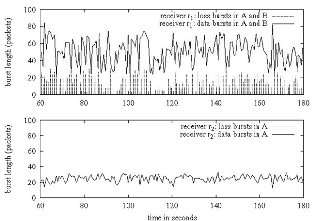
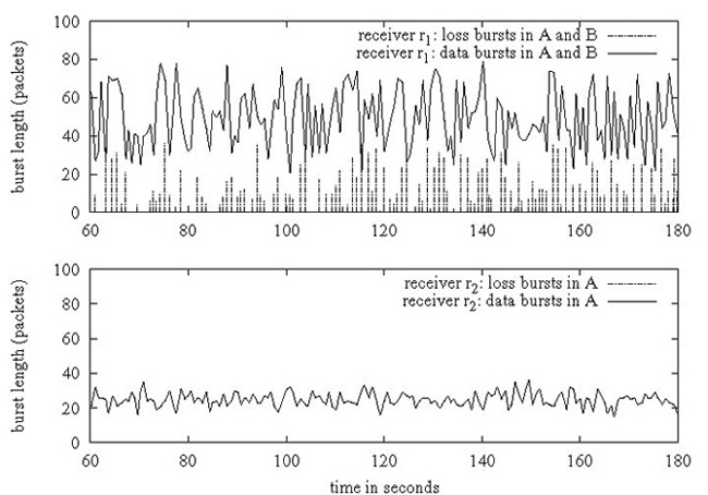
(a) Cornell 64-node Cluster (b) Utah Emulab Testbed
Figure 1: Datacenter Loss is bursty and uncorrelated across nodes: receiver r1 (top) joins groups A and B and exhibits bursty loss, whereas receiver r2 (bottom) joins only group A and experiences zero loss.
We consider patterns of multicast usage where each node is in many different groups of small to medium size (10 to 50 nodes). Following the IP Multicast model, a group is defined as a set of receivers for multicast data, and senders do not have to belong to the group to send to it. We expect each node to receive data from a large set of distinct senders, across all the groups it belongs to.
Where does Loss occur in a Datacenter? Datacenter networks have flat routing structures with no more than two or three hops on any end-to-end path. They are typically over-provisioned and of high quality, and packet loss in the network is almost non-existent. In contrast, datacenter end-hosts are inexpensive and easily overloaded; even with high-capacity network interfaces, the commodity OS often drops packets due to buffer overflows caused by traffic spikes or high-priority threads occupying the CPU. Hence, our loss model is one of short packet bursts dropped at the end-host receivers at varying loss rates.
Figure 1 strongly indicates that loss in a datacenter is (a) bursty and (b) independent across end-hosts. In this experiment, a receiver r1 joins two multicast groups A and B, and another receiver r2 in the same switching segment joins only group A. From a sender located multiple switches away on the network, we send per-second data bursts of around 25 1KB packets to group A and simultaneously send a burst of 0-50 packets to group B, and measure packet loss at both receivers. We ran this experiment on two networks: a 64-node cluster at Cornell with 1.3 Ghz receivers and the Emulab testbed at Utah with 2 Ghz receivers, all nodes running Linux 2.6.12.
The top graphs in Figure 1 show the traffic bursts and loss bursts at receiver r1, and the bottom graphs show the same information for r2. We can see that r1 gets overloaded and drops packets in bursts of size 1-30 packets, whereas r2 does not drop any packets — importantly, around 30% of the packets dropped by r1 are in group A, which is common to both receivers. Hence, loss is both bursty and independent across nodes. Together, these graphs indicate strongly that loss occurs due to buffer overflows at receiver r1.
The example in Figure 1 is simplistic - each incoming burst of traffic arrives at the receiver within a small number of milliseconds - but conveys a powerful message: it is very easy to trigger significant bursty loss at datacenter end-hosts. The receivers in these experiments were running empty and draining packets continuously out of the kernel, with zero contention for the CPU or the network, whereas the settings of interest to us involve time-critical, possibly CPU-intensive applications running on top of the communication stack.
Further, we expect multi-group settings to intrinsically exhibit bursty incoming traffic of the kind emulated in this experiment — each node in the system receives data from multiple senders in multiple groups and it is likely that the inter-arrival time of data packets at a node will vary widely, even if the traffic rate at one sender or group is steady. In some cases, burstiness of traffic could also occur due to time-critical application behavior - for example, imagine an update in the value of a stock quote triggering off activity in several system components, which then multicast information to a replicated central datastore. If we assume that each time-critical component processes the update within a few hundred microseconds, and that inter-node socket-to-socket latency is around fifty microseconds (an actual number from our experimental cluster), the central datastore could easily see a sub-millisecond burst of traffic. In this case, the componentized structure of the application resulted in bursty traffic; in other scenarios, the application domain could be intrinsically prone to bursty input. For example, a financial calculator tracking a set of hundred equities with correlated movements might expect to receive a burst of a hundred packets in multiple groups almost instantaneously.
3 The Design of a Time-Critical Multicast Primitive
In recent years, multicast research has focused almost exclusively on application-level routing mechanisms, or overlay networks ([13] is one example), designed to operate in the wide-area without any existing router support. The need for overlay multicast stems from the lack of IP Multicast coverage in the modern internet, which in turn reflects concerns of administration complexity, scalability, and the risk of multicast `storms' caused by misbehaving nodes. However, the homogeneity and comparatively limited size of datacenter networks pose few scalability and administration challenges to IP Multicast, making it a viable and attractive option in such settings. In this paper, we restrict ourselves to a more traditional definition of `reliable multicast', as a reliability layer over IP Multicast. Given that the selection of datacenter hardware is typically influenced by commercial constraints, we believe that any viable solution for this context must be able to run on any mix of existing commodity routers and OS software; hence, we focus exclusively on mechanisms that act at the application-level, ruling out schemes which require router modification, such as PGM [19].
3.1 The Timeliness of (Scalable) Reliable Multicast Protocols
Reliable multicast protocols typically consist of three logical phases: transmission of the packet, discovery of packet loss, and recovery from it. Recovery is a fairly fast operation; once a node knows it is missing a packet, recovering it involves retrieving the packet from some other node. However, in most existing scalable multicast protocols, the time taken to discover packet loss dominates recovery latency heavily in the kind of settings we are interested in. The key insight is that the discovery latency of reliable multicast protocols is usually inversely dependent on data rate: for existing protocols, the rate of outgoing data at a single sender in a single group. Existing schemes for reliability in multicast can be roughly divided into the following categories:
ACK/timeout: RMTP [21], RMTP-II [22]. In this approach, receivers send back ACKs (acknowledgements) to the sender of the multicast. This is the trivial extension of unicast reliability to multicast, and is intrinsically unscalable due to ACK implosion; for each sent message, the sender has to process an ACK from every receiver in the group [21]. One work-around is to use ACK aggregation, which allows such solutions to scale in the number of receivers but requires the construction of a tree for every sender to a group. Also, any aggregative mechanism introduces latency, leading to larger time-outs at the sender and delaying loss discovery; hence, ACK trees are unsuitable in time-critical settings.
Gossip-Based: Bimodal Multicast [10], lpbcast [17]. Receivers periodically gossip histories of received packets with each other. Upon receiving a digest, a receiver compares the contents with its own packet history, sending any packets that are missing from the gossiped history and requesting transmission of any packets missing from its own history. Gossip-based schemes offer scalability in the number of receivers per group, and extreme resilience by diffusing the responsibility of ensuring reliability for each packet over the entire set of receivers. However, they are not designed for time-critical settings: discovery latency is equal to the time period between gossip exchanges (a significant number of milliseconds - 100ms in Bimodal Multicast [10]), and recovery involves a further one or two-phase interaction as the affected node obtains the packet from its gossip contact.
NAK/Sender-based Sequencing: SRM [18]. Senders number outgoing multicasts, and receivers discover packet loss when a subsequent message arrives. Loss discovery latency is thus proportional to the inter-send time at any single sender to a single group - a receiver can't discover a loss in a group until it receives the next packet from the same sender to that group - and consequently depends on the sender's data transmission rate to the group. To illustrate this point, we measured the performance of SRM as we increased the number of groups each node belonged in, keeping the throughput in the system constant by reducing the data rate within each group - as Figure 2 shows, discovery latency of lost packets degrades linearly as each node's bandwidth is increasingly fragmented and each group's rate goes down, increasing the time between two consecutive sends by a sender to the same group. Once discovery occurs in SRM, lost packet recovery is initiated by the receiver, which uses IP multicast (with a suitable TTL value); the sender (or some other receiver), responds with a retransmission, also using IP multicast.
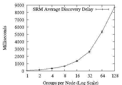
Figure 2: SRM's Discovery Latency vs. Groups per Node, on a 64-node cluster, with groups of 10 nodes each. Error bars are min and max over 10 runs.
Sender-based FEC [20, 23]: Forward Error Correction schemes involve multicasting redundant error correction information along with data packets, so that receivers can recover lost packets without contacting the sender or any other node. FEC mechanisms involve generating c repair packets for every r data packets, such that any r of the combined set of r+c data and repair packets is sufficient to recover the original r data packets; we term this (r, c) parameter the rate-of-fire. FEC mechanisms have the benefit of tunability, providing a coherent relationship between overhead and timeliness - the more the number of repair packets generated, the higher the probability of recovering lost packets from the FEC data. Further, FEC based protocols are very stable under stress, since recovery does not induce large degrees of extra traffic. As in NAK protocols, the timeliness of FEC recovery depends on the data transmission rate of a single sender in a single group; the sender can send a repair packet to a group only after sending out r data packets to that group. Fast, efficient encodings such as Tornado codes [11] make sender-based FEC a very attractive option in multicast applications involving a single, dedicated sender; for example, software distribution or internet radio.
Receiver-based FEC [9]: Of the above schemes, ACK-based protocols are intrinsically unsuited for time-critical multi-sender settings, while sender-based sequencing and FEC limit discovery latency to inter-send time at a single sender within a single group. Ideally, we would like discovery latency to be independent of inter-send time, and combine the scalability of a gossip-based scheme with the tunability of FEC. Receiver-based FEC, first introduced in the Slingshot protocol [9], provides such a combination: receivers generate FEC packets from incoming data and exchange these with other randomly chosen receivers. Since FEC packets are generated from incoming data at a receiver, the timeliness of loss recovery depends on the rate of data multicast in the entire group, rather than the rate at any given sender, allowing scalability in the number of senders to the group.
Slingshot is aimed at single-group settings, recovering from packet loss in time proportional to that group's data rate. Our goal with Ricochet is to achieve recovery latency dependent on the rate of data incoming at a node across all groups. Essentially, we want recovery of packets to occur as quickly in a thousand 10 Kbps groups as in a single 10 Mbps group, allowing applications to divide node bandwidth among thousands of multicast groups while maintaining time-critical packet recovery. To achieve this, we introduce Lateral Error Correction, a new form of receiver-generated FEC that probabilistically combines receiver-generated repair traffic across multiple groups to drive down packet recovery latencies.
4 Lateral Error Correction and the Ricochet protocol
In Ricochet, each node belongs to a number of groups, and receives data multicast within any of them. The basic operation of the protocol involves generating XORs from incoming data and exchanging them with other randomly selected nodes. Ricochet operates using two different packet types: data packets - the actual data multicast within a group - and repair packets, which contain recovery information for multiple data packets. Figure 3 shows the structure of these two packet types. Each data packet header contains a packet identifier - a (sender, group, sequence number) tuple that identifies it uniquely. A repair packet contains an XOR of multiple data packets, along with a list of their identifiers - we say that the repair packet is composed from these data packets, and that the data packets are included in the repair packet. An XOR repair composed from r data packets allows recovery of one of them, if all the other r−1 data packets are available; the missing data packet is obtained by simply computing the XOR of the repair's payload with the other data packets.
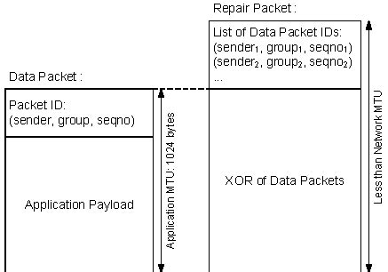
Figure 3: Ricochet Packet Structure
At the core of Ricochet is the LEC engine running at each node that decides on the composition and destinations of repair packets, creating them from incoming data across multiple groups. The operating principle behind LEC is the notion that repair packets sent by a node to another node can be composed from data in any of the multicast groups that are common to them. This allows recovery of lost packets at the receiver of the repair packet to occur within time that's inversely proportional to the aggregate rate of data in all these groups. Figure 4 illustrates this idea: n1 has groups A and B in common with n2, and hence it can generate and dispatch repair packets that contain data from both these groups. n1 needs to wait only until it receives 5 data packets in either A or B before it sends a repair packet, allowing faster recovery of lost packets at n2.
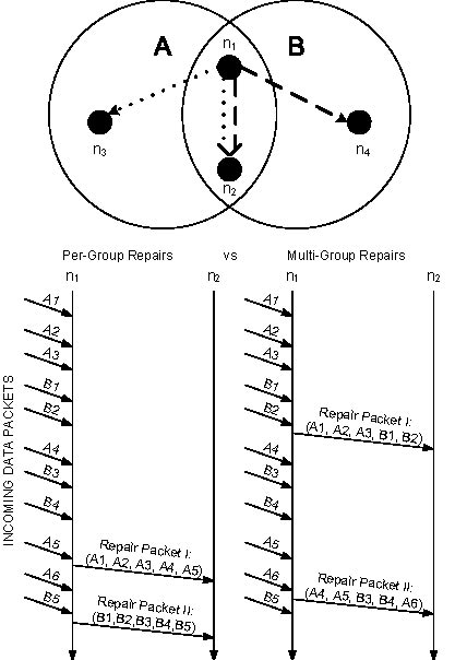
Figure 4: LEC in 2 Groups: Receiver n1 can send repairs to n2 that combine data from both groups A and B.
While combining data from different groups in outgoing repair packets drives down recovery time, it tampers with the coherent tunability that single group receiver-based FEC provides. The rate-of-fire parameter in receiver-based FEC provides a clear, coherent relationship between overhead and recovery percentage; for every r data packets, c repair packets are generated in the system, resulting in some computable probability of recovering from packet loss. The challenge for LEC is to combine repair traffic for multiple groups while retaining per-group overhead and recovery percentages, so that each individual group can maintain its own rate-of-fire. To do so, we abstract out the essential properties of receiver-based FEC that we wish to maintain:
1. Coherent, Tunable Per-Group Overhead: For every data packet that a node receives in a group with rate-of-fire (r, c), it sends out an average of c repair packets including that data packet to other nodes in the group.
2. Randomness: Destination nodes for repair packets are picked randomly, with no node receiving more or less repairs than any other node, on average.
LEC supports overlapping groups with the same r component and different c values in their rate-of-fire parameter. In LEC, the rate-of-fire parameter is translated into the following guarantee: For every data packet d that a node receives in a group with rate-of-fire (r, c), it selects an average of c nodes from the group randomly and sends each of these nodes exactly one repair packet that includes d. In other words, the node sends an average of c repair packets containing d to the group. In the following section, we describe the algorithm that LEC uses to compose and dispatch repair packets while maintaining this guarantee.
4.1 Algorithm Overview
Ricochet is a symmetric protocol - exactly the same LEC algorithm and supporting code runs at every node - and hence, we can describe its operation from the vantage point of a single node, n1.
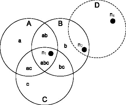
Figure 5: n1 belongs to groups A, B, C: it divides them into disjoint regions abc, ab, ac, bc, a, b, c
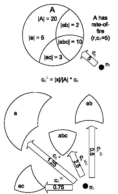
Figure 6: n1 selects proportionally sized chunks of cA from the regions of A
The LEC engine running at n1 divides n1's neighborhood - the set of nodes it shares one or more multicast groups with - into regions, and uses this information to construct and disseminate repair packets. Regions are simply the disjoint intersections of all the groups that n1 belongs to. Figure 5 shows the regions in a hypothetical system, where n1 is in three groups, A, B and C. We denote groups by upper-case letters and regions by the concatenation of the group names in lowercase; i.e, abc is a region formed by the intersection of A, B and C. In our example, the neighborhood set of n1 is carved into seven regions: abc, ac, ab, bc, a, b and c, essentially the power set of the set of groups involved. Readers may be alarmed that this transformation results in an exponential number of regions, but this is not the case; we are only concerned with non-empty intersections, the cardinality of which is bounded by the number of nodes in the system, as each node belongs to exactly one intersection (see Section 4.1.4). Note that n1 does not belong to group D and is oblivious to it; it observes n2 as belonging to region b, rather than bd, and is not aware of n4's existence.
4.1.2 Selecting targets from regions, not groups
Instead of selecting targets for repairs randomly from the entire group, LEC selects targets randomly from each region. The number of targets selected from a region is set such that:
1. It is proportional to the size of the region
2. The total number of targets selected, across regions, is equal to the c value of the group
Hence, for a given group A with rate-of-fire (r, cA), the number of targets selected by LEC in a particular region, say abc, is equal to cA * |abc|/|A|, where |x| is the number of nodes in the region or group x. We denote the number of targets selected by LEC in region abc for packets in group A as cAabc. Figure 6 shows n1 selecting targets for repairs from the regions of A.
Note that LEC may pick a different number of targets from a region for packets in a different group; for example, cAabc differs from cBabc. Selecting targets in this manner also preserves randomness of selection; if we rephrase the task of target selection as a sampling problem, where a random sample of size c has to be selected from the group, selecting targets from regions corresponds to stratified sampling [14], a technique from statistical theory.
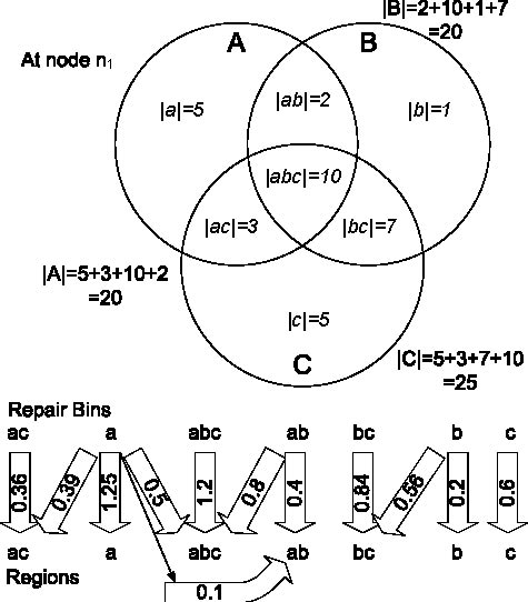
Figure 7: Mappings between repair bins and regions: the repair bin for ab selects 0.4 targets from region ab and 0.8 from abc for every repair packet. Here, cA=5, cB=4, and cC=3.
4.1.3 Why select targets from regions?
Selecting targets from regions instead of groups allows LEC to construct repair packets from multiple groups; since we know that all nodes in region ab are interested in data from groups A and B, we can create composite repair packets from incoming data packets in both groups and send them to nodes in that region.
Single-group receiver-based FEC [9] is implemented using a simple construct called a repair bin, which collects incoming data within the group. When a repair bin reaches a threshold size of r, a repair packet is generated from its contents and sent to c randomly selected nodes in the group, after which the bin is cleared. Extending the repair bin construct to regions seems simple; a bin can be maintained for each region, collecting data packets received in any of the groups composing that region. When the bin fills up to size r, it can generate a repair packet containing data from all these groups, and send it to targets selected from within the region.
Using per-region repair bins raises an interesting question: if we construct a composite repair packet from data in groups A, B, and C, how many targets should we select from region abc for this repair packet - cAabc, cBabc, or cCabc? One possible solution is to pick the maximum of these values. If cAabc ≥ cBabc ≥ cCabc, then we would select cAabc. However, a data packet in group B, when added to the repair bin for the region abc would be sent to an average of cAabc targets in the region; resulting in more repair packets containing that data packet sent to the region than required (cBabc), which results in more repair packets sent to the entire group. Hence, more overhead is expended per data packet in group B than required by its (r, cB) value; a similar argument holds for data packets in group C as well.
Instead, we choose the minimum of values; this, as expected, results in a lower level of overhead for groups A and B than required, resulting in a lower fraction of packets recovered from LEC. To rectify this we send the additional compensating repair packets to the region abc from the repair bins for regions a and b. The repair bin for region a would select cAabc − cCabc destinations, on an average, for every repair packet it generates; this is in addition to the cAa destinations it selects from region a.
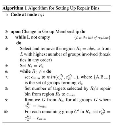
A more sophisticated version of the above strategy involves iteratively obtaining the required repair packets from regions involving the remaining groups; for instance, we would have the repair bin for ab select the minimum of cAabc and cBabc - which happens to be cBabc - from abc, and then have the repair bin for a select the remainder value, cAabc − cBabc, from abc. Algorithm 1 illustrates the final approach adopted by LEC, and Figure 7 shows the output of this algorithm for an example scenario. A repair bin selects a non-integral number of nodes from an intersection by alternating between its floor and ceiling probabilistically, in order to maintain the average at that number.
4.1.4 Complexity
The algorithm described above is run every time nodes join or leave any of the multicast groups that n1 is part of. The algorithm has complexity O(I ⋅ d), where I is the number of populated regions (i.e, with one or more nodes in them), and d is the maximum number of groups that form a region. Note that I at n1 is bounded from above by the cardinality of the set of nodes that share a multicast group with n1, since regions are disjoint and each node exists in exactly one of them. d is bounded by the number of groups that n1 belongs to.
4.2 Implementation Details
Our implementation of Ricochet is in Java. Below, we discuss the details of the implementation, along with the performance optimizations involved - some obvious and others subtle.
4.2.1 Repair Bins
A Ricochet repair bin is a lightweight structure holding an XOR and a list of data packets, and supporting an add operation that takes in a data packet and includes it in the internal state. The repair bin is associated with a particular region, receiving all data packets incoming in any of the groups forming that region. It has a list of regions from which it selects targets for repair packets; each of these regions is associated with a value, which is the average number of targets which must be selected from that region for an outgoing repair packet. In most cases, as shown in Figure 7, the value associated with a region is not an integer; as mentioned before, the repair bin alternates between the floor and the ceiling of the value to maintain the average at the value itself. For example, in Figure 7, the repair bin for abc has to select 1.2 targets from abc, on average; hence, it generates a random number between 0 and 1 for each outgoing repair packet, selecting 1 node if the random number is more than 0.2, and 2 nodes otherwise.
4.2.2 Staggering for Bursty Loss
A crucial algorithmic optimization in Ricochet is staggering - also known as interleaving [23] - which provides resilience to bursty loss. Given a sequence of data packets to encode, a stagger of 2 would entail constructing one repair packet from the 1st, 3rd, 5th... packets, and another repair packet from the 2nd, 4th, 6th... packets. The stagger value defines the number of repairs simultaneously being constructed, as well as the distance in the sequence between two data packets included in the same repair packet. Consequently, a stagger of i allows us to tolerate a loss burst of size i while resulting in a proportional slowdown in recovery latency, since we now have to wait for O(i*r) data packets before despatching repair packets.
In conventional sender-based FEC, staggering is not a very attractive option, providing tolerance to very small bursts at the cost of multiplying the already prohibitive loss discovery latency. However, LEC recovers packets so quickly that we can tolerate a slowdown of a factor of ten without leaving the tens of milliseconds range; additionally, a small stagger at the sender allows us to tolerate very large bursts of lost packets at the receiver, especially since the burst is dissipated among multiple groups and senders. Ricochet implements a stagger of i by the simple expedient of duplicating each logical repair bin into i instances; when a data packet is added to the logical repair bin, it is actually added to a particular instance of the repair bin, chosen in round-robin fashion. Instances of a duplicated repair bin behave exactly as single repair bins do, generating repair packets and sending them to regions when they get filled up.
4.2.3 Multi-Group Views
Each Ricochet node has a multi-group view, which contains membership information about other nodes in the system that share one or more multicast groups with it. In traditional group communication literature, a view is simply a list of members in a single group [24]; in contrast, a Ricochet node's multi-group view divides the groups that it belongs to into a number of regions, and contains a list of members lying in each region. Ricochet uses the multi-group view at a node to determine the sizes of regions and groups, to set up repair bins using the LEC algorithm. Also, the per-region lists in the multi-view are used to select destinations for repair packets. The multi-group view at n1 - and consequently the group and intersection sizes - does not include n1 itself.
4.2.4 Membership and Failure Detection
Ricochet can plug into any existing membership and failure detection infrastructure, as long as it is provided with reasonably up-to-date views of per-group membership by some external service. In our implementation, we use simple versions of Group Membership (GMS) and Failure Detection (FD) services, which execute on high-end server machines. If the GMS receives a notification from the FD that a node has failed, or it receives a join/leave to a group from a node, it sends an update to all nodes in the affected group(s). The GMS is not aware of regions; it maintains conventional per-group lists of nodes, and sends per-group updates when membership changes. For example, if node n55 joins group A, the update sent by the GMS to every node in A would be a 3-tuple: (Join, A, n55). Individual nodes process these updates to construct multi-group views relative to their own membership.
Since the GMS does not maintain region data, it has to scale only in the number of groups in the system; this can be easily done by partitioning the service on group id and running each partition on a different server. For instance, one machine is responsible for groups A and B, another for C and D, and so on. Similarly, the FD can be partitioned on a topological criterion; one machine on each rack is responsible for monitoring other nodes on the rack by pinging them periodically. For fault-tolerance, each partition of the GMS can be replicated on multiple machines using a strongly consistent protocol like Paxos. The FD can have a hierarchical structure to recover from failures; a smaller set of machines ping the per-rack failure detectors, and each other in a chain. We believe that such a semi-centralized solution is appropriate and sufficient in a datacenter setting, where connectivity and membership are typically stable. Crucially, the protocol itself does not need consistent membership, and degrades gracefully with the degree of inconsistency in the views; if a failed node is included in a view, performance will dip fractionally in all the groups it belongs to as the repairs sent to it by other nodes are wasted.
(a) 10% Loss Rate (b) 15% Loss Rate (c) 20% Loss Rate
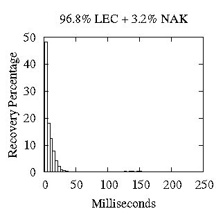
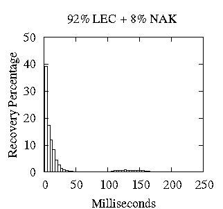
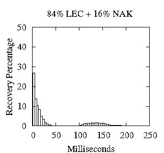
Figure 8: Distribution of Recoveries: LEC + NAK for varying degrees of loss
4.2.5 Performance
Since Ricochet creates LEC information from each incoming data packet, the critical communication path that a data packet follows within the protocol is vital in determining eventual recovery times and the maximum sustainable throughput. XORs are computed in each repair bin incrementally, as packets are added to the bin. A crucial optimization used is pre-computation of the number of destinations that the repair bin sends out a repair to, across all the regions that it sends repairs to: Instead of constructing a repair and deciding on the number of destinations once the bin fills up, the repair bin precomputes this number and constructs the repair only if the number is greater than 0. When the bin overflows and clears itself, the expected number of destinations for the next repair packet is generated. This restricts the average number of two-input XORs per data packet to c (from the rate-of-fire) in the worst case - which occurs when no single repair bin selects more than 1 destination, and hence each outgoing repair packet is a unique XOR.
4.2.6 Buffering and Loss Control
LEC - like any other form of FEC - works best when losses are not in concentrated bursts. Ricochet maintains an application-level buffer with the aim of minimizing in-kernel losses, serviced by a separate thread that continuously drains packets from the kernel. If memory at end-hosts is constrained and the application-level buffer is bounded, we use customized packet-drop policies to handle overflows: a randomly selected packet from the buffer is dropped and the new packet is accommodated instead. In practice, this results in a sequence of almost random losses from the buffer, which are easy to recover using FEC traffic. Whether the application-level buffer is bounded or not, it ensures that packet losses in the kernel are reduced to short bursts that occur only during periods of overload or CPU contention. We evaluate Ricochet against loss bursts of upto 100 packets, though in practice we expect the kind of loss pattern shown in 1, where few bursts are greater than 20-30 packets, even with highly concentrated traffic spikes.
4.2.7 NAK Layer for 100% Recovery
Ricochet recovers a high percentage of lost packets via the proactive LEC traffic; for certain applications, this probabilistic guarantee of packet recovery is sufficient and even desirable in cases where data `expires' and there is no utility in recovering it after a certain number of milliseconds. However, the majority of applications require 100% recovery of lost data, and Ricochet uses a reactive NAK layer to provide this guarantee. If a receiver does not recover a packet through LEC traffic within a timeout period after discovery of loss, it sends an explicit NAK to the sender and requests a retransmission. While this NAK layer does result in extra reactive repair traffic, two factors separate it from traditional NAK mechanisms: firstly, recovery can potentially occur very quickly - within a few hundred milliseconds - since for almost all lost packets discovery of loss takes place within milliseconds through LEC traffic. Secondly, the NAK layer is meant solely as a backup mechanism for LEC and responsible for recovering a very small percentage of total loss, and hence the extra overhead is minimal.
4.2.8 Optimizations
Ricochet maintains a buffer of unusable repair packets that enable it to utilize incoming repair packets better. If one repair packet is missing exactly one more data packet than another repair packet, and both are missing at least one data packet, Ricochet obtains the extra data packet by XORing the two repair packets. Also, it maintains a list of unusable repair packets which is checked intermittently to see if recent data packet recoveries and receives have made any old repair packets usable.
4.2.9 Message Ordering
As presented, Ricochet provides multicast reliability but does not deliver messages in the same order at all receivers. We are primarily concerned with building an extremely rapid multicast primitive that can be used by applications that require unordered reliable delivery as well as layered under ordering protocols with stronger delivery properties. For instance, Ricochet can be used as a reliable transport by any of the existing mechanisms for total ordering [16] — in separate work [8], we describe one such technique that predicts out-of-order delivery in datacenters to optimize ordering delays.
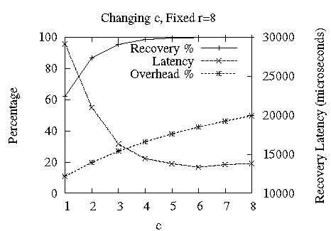
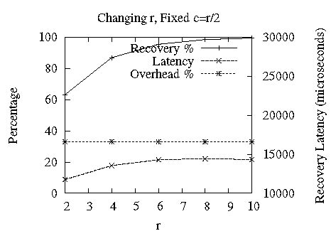
Figure 9: Tuning LEC : tradeoff points available between recovery %, overhead % (left y-axis) and avg recovery latency (right y-axis) by changing the rate-of-fire ( r, c).
5 Evaluation
We evaluated our Java implementation of Ricochet on a 64-node cluster, comprising of four racks of 16 nodes each, interconnected via two levels of switches. Each node has a single 1.3 Ghz CPU with 512 Mb RAM, runs Linux 2.6.12 and has two 100 Mbps network interfaces, one for control and the other for experimental traffic. Typical socket-to-socket latency within the cluster is around 50 microseconds. In the following experiments, for a given loss rate L, three different loss models are used:
⋅ uniform - also known as the Bernoulli model [25] - refers to dropping packets with uniform probability equal to the loss rate L.
⋅ bursty involves dropping packets in equal bursts of length b. The probability of starting a loss burst is set so that each burst is of exactly b packets and the loss rate is maintained at L. This is not a realistic model but allows us to precisely measure performance relative to specific burst lengths.
⋅ markov drops packets using a simple 2-state markov chain, where each node alternates between a lossy and a lossless state, and the probabilities are set so that the average length of a loss burst is m and the loss rate is L, as described in [25].
In experiments with multiple groups, nodes are assigned to groups at random, and the following formula is used to relate the variables in the grouping pattern: n*d=g*s, where n is the number of nodes in the system (64 in most of the experiments), d is the degree of membership, i.e. the number of groups each node joins, g is the total number of groups in the system, and s is the average size of each group. For example, in a 16-node setting where each node joins 512 groups and each group is of size 8, g is set to 16*512/8 ≈ 1024. Each node is then assigned to 512 randomly picked groups out of 1024. Hence, the grouping patterns for each experiment is completely represented by a (n,d,s) tuple.
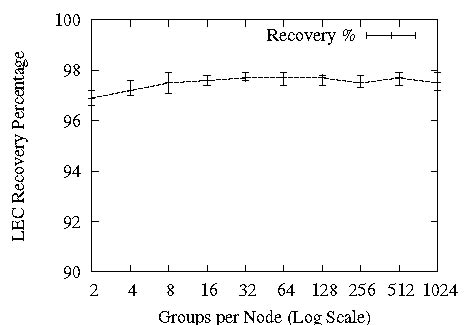
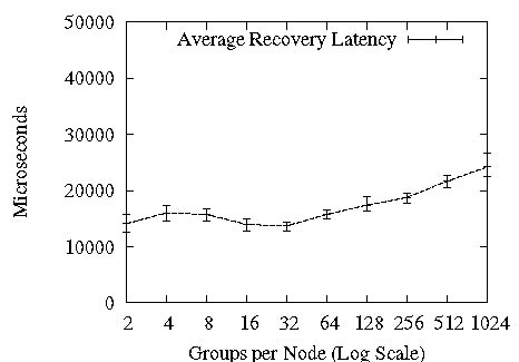
Figure 10: Scalability in Groups
For every run, we set the sending rate at a node such that the total system rate of incoming messages is 64000 packets per second, or 1000 packets per node per second. Data packets are 1K bytes in size. Each point in the following graphs - other than Figure 8, which shows distributions for single runs - is an average of 5 runs. A run lasts 30 seconds and produces ≈ 2 million receive events in the system.
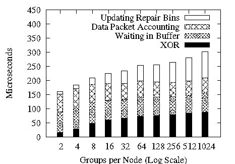
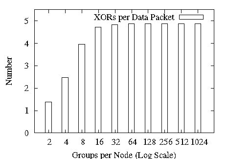
Figure 11: CPU time and XORs per data packet
5.1 Distribution of Recoveries in Ricochet
First, we provide a snapshot of what typical packet recovery timelines look like in Ricochet. Earlier, we made the assertion that Ricochet discovers the loss of almost all packets very quickly through LEC traffic, recovers a majority of these instantly and recovers the remainder using an optional NAK layer. In Figure 8, we show the histogram of packet recovery latencies for a 16-node run with degree of membership d=128 and group size s=10. We use a simplistic NAK layer that starts unicasting NAKs to the original sender of the multicast 100 milliseconds after discovery of loss, and retries at 50 millisecond intervals. Figure 8 shows three scenarios: under uniform loss rates of 10%, 15%, and 20%, different fractions of packet loss are recovered through LEC and the remainder via reactive NAKs. These graphs illustrate the meaning of the LEC recovery percentage: if this number is high, more packets are recovered very quickly without extra traffic in the initial segment of the graphs, and less reactive overhead is induced by the NAK layer. Importantly, even with a recovery percentage as low as 84% in Figure 8(c), we are able to recover all packets within 250 milliseconds with a crude NAK layer due to early LEC-based discovery of loss. For the remaining experiments, we will switch the NAK layer off and focus solely on LEC performance; also, since we found this distribution of recovery latencies to be fairly representative, we present only the percentage of lost packets recovered using LEC and the average latency of these recoveries. Experiment Setup: (n=16, d=128, s=10), Loss Model: Uniform, [10%, 15%, 20%].
5.2 Tunability of LEC in multiple groups
The Slingshot protocol [9] illustrated the tunability of receiver-generated FEC for a single group; we include a similar graph for Ricochet in Figure 9, showing that the rate-of-fire parameter (r,c) provides a knob to tune LEC's recovery characteristics. In Figure 9.a, we can see that increasing the c value for constant r=8 increases the recovery percentage and lowers recovery latency by expending more overhead - measured as the percentage of repair packets to all packets. In Figure 9.b, we see the impact of increasing r, keeping the ratio of c to r - and consequently, the overhead - constant. For the rest of the experiments, we set the rate-of-fire at (r=8,c=5). Experiment Setup: (n=64,d=128,s=10), Loss Model: Uniform, 1%.
5.3 Scalability
Next, we examine the scalability of Ricochet to large numbers of groups. Figure 10 shows that increasing the degree of membership for each node from 2 to 1024 has almost no effect on the percentage of packets recovered via LEC, and causes a slow increase in average recovery latency. The x-axis in these graphs is log-scale, and hence a straight line increase is actually logarithmic with respect to the number of groups and represents excellent scalability. The increase in recovery latency towards the right side of the graph is due to Ricochet having to deal internally with the representation of large numbers of groups; we examine this phenomenon later in this section.
For a comparison point, we refer readers back to SRM's discovery latency in Figure 2: in 128 groups, SRM discovery took place at 9 seconds. In our experiments, SRM recovery took place roughly 4 seconds after discovery in all cases. While fine-tuning the SRM implementation for clustered settings should eliminate that 4 second gap between discovery and recovery, at 128 groups Ricochet surpasses SRM's best possible recovery performance of 5 seconds by between 2 and 3 orders of magnitude.
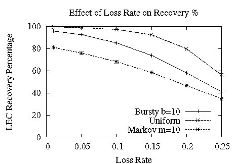
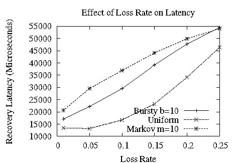
Figure 12: Impact of Loss Rate on LEC
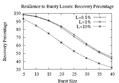
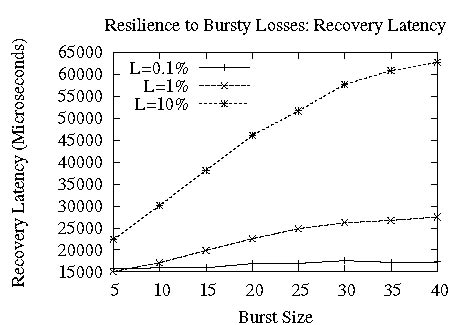
Figure 13: Resilience to Burstiness
Though Ricochet's recovery characteristics scale well in the number of groups, it is important that the computational overhead imposed by the protocol on nodes stays manageable, given that time-critical applications are expected to run over it. Figure 11 shows the scalability of an important metric: the time taken to process a single data packet. The straight line increase against a log x-axis shows that per-packet processing time increases logarithmically with the number of groups - doubling the number of groups results in a constant increase in processing time. The increase in processing time towards the latter half of the graph is due to the increase in the number of repair bins with the number of groups. While we considered 1024 groups adequate scalability, Ricochet can potentially scale to more groups with further optimization, such as creating bins only for occupied regions. In the current implementation, per-packet processing time goes from 160 microseconds for 2 groups to 300 microseconds for 1024, supporting throughput exceeding a thousand packets per second. Figure 11 also shows the average number of XORs per incoming data packet. As stated in section 4.2.2, the number of XORs stays under 5 - the value of c from the rate-of-fire (r,c). Experiment Setup: (n=64, d=*, s=10), Loss Model: Uniform, 1%.
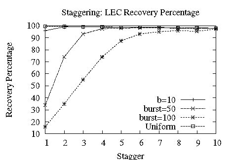
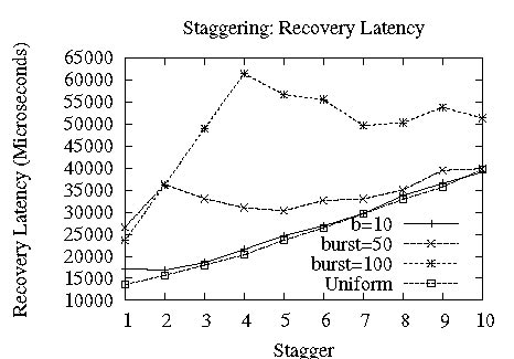
Figure 14: Staggering allows Ricochet to recover from long bursts of loss.
5.4 Loss Rate and LEC Effectiveness
Figure 12 shows the impact of the Loss Rate on LEC recovery characteristics, under the three loss models. Both LEC recovery percentages and latencies degrade gracefully: with an unrealistically high loss rate of 25%, Ricochet still recovers 40% of lost packets at an average of 60 milliseconds. For uniform and bursty loss models, recovery percentage stays above 90% with a 5% loss rate; markov does not fare as well, even at 1% loss rate, primarily because it induces bursts much longer than its average of 10 - the max burst in this setting averages at 50 packets. Experiment Setup: (n=64, d=128, s=10), Loss Model: *.
5.5 Resilience to Bursty Losses
As we noted before, a major criticism of FEC schemes is their fragility in the face of bursty packet loss. Figure 13 shows that Ricochet is naturally resilient to small loss bursts, without the stagger optimization - however, as the burst size increases, the percentage of packets recovered using LEC degrades substantially. Experiment Setup: (n=64, d=128, s=10), Loss Model: Bursty.
However, switching on the stagger optimization described in Section 4.2.2 increases Ricochet's resilience to burstiness tremendously, without impacting recovery latency much. Figure 14 shows that setting an appropriate stagger value allows Ricochet to handle large bursts of loss: for a burst size as large as 100, a stagger of 6 enables recovery of more than 90% lost packets at an average latency of around 50 milliseconds. Experiment Setup: (n=64, d=128, s=10), Loss Model: Bursty, 1%.
5.6 Effect of Group and System Size
What happens to LEC performance when the average group size in the cluster is large compared to the total number of nodes? Figure 15 shows that recovery percentages are almost unaffected, staying above 99% in this scenario, but recovery latency is impacted by more than a factor of 2 as we triple group size from 16 to 48 in a 64-node setting. Note that this measures the impact of the size of the group relative to the entire system; receiver-based FEC has been shown to scale well in a single isolated group to hundreds of nodes [9]. Experiment Setup: (n=64, d=128, s=*), Loss Model: Uniform, 1%.
While we could not evaluate to system sizes beyond 64 nodes, Ricochet should be oblivious to the size of the entire system, since each node is only concerned with the groups it belongs to. We ran 4 instances of Ricochet on each node to obtain an emulated 256 node system with each instance in 128 groups, and the resulting recovery percentage of 98% - albeit with a degraded average recovery latency of nearly 200 milliseconds due to network and CPU contention - confirmed our intuition of the protocol's fundamental insensitivity to system size.
6 Future Work
One avenue of research involves embedding more complex error codes such as Tornado [11] in LEC; however, the use of XOR has significant implications for the design of the algorithm, and using a different encoding might require significant changes. LEC uses XOR for its simplicity and speed, and as our evaluation showed, we obtain properties on par with more sophisticated encodings, including tunability and burst resilience. We plan on replacing our simplistic NAK layer with a version optimized for bulk transfer, providing an efficient backup for LEC when sustained bursts occur of hundreds of packets or more. Another line of work involves making the parameters for LEC - such as rate-of-fire and stagger - adaptive, reacting to meet varying load and network characteristics. We are currently working with industry partners to layer Ricochet under data distribution, publish-subscribe and web-service interfaces, as well as building protocols with stronger ordering and atomicity properties over it.
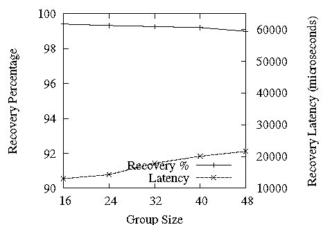
Figure 15: Effect of Group Size
7 Conclusion
We believe that the next generation of time-critical applications will execute on commodity clusters, using the techniques of massive redundancy, fault-tolerance and scalable communication currently available to distributed systems practitioners. Such applications will require a multicast primitive that delivers data at the speed of hardware multicast in failure-free operation and recovers from packet loss within milliseconds irrespective of the pattern of usage. Ricochet provides applications with massive scalability in multiple dimensions - crucially, it scales in the number of groups in the system, performing well under arbitrary grouping patterns and overlaps. A clustered communication primitive with good timing properties can ultimately be of use to applications in diverse domains not normally considered time-critical - e-tailers, online web-servers and enterprise applications, to name a few.
Acknowledgments
We received invaluable comments from Dave Andersen, Danny Dolev, Tudor Marian, Art Munson, Robbert van Renesse, Emin Gun Sirer, Niraj Tolia and Einar Vollset. We would like to thank our shepherd Mike Dahlin, as well as all the anonymous reviewers of the paper.
References
- [1]
-
Bea weblogic.
http://www.bea.com/framework.jsp?CNT=index.htm&FP=/content/products/web%
logic, 2006.
- [2]
-
Gemstone gemfire.
http://www.gemstone.com/products/gemfire/enterprise.php, 2006.
- [3]
-
Ibm websphere.
www.ibm.com/software/webservers/appserv/was/, 2006.
- [4]
-
Jboss.
http://labs.jboss.com/portal/, 2006.
- [5]
-
Real-time innovations data distribution service.
http://www.rti.com/products/data_distribution/index.html, 2006.
- [6]
-
Tangosol coherence.
http://www.tangosol.com/html/coherence-overview.shtml, 2006.
- [7]
-
Tibco rendezvous.
http://www.tibco.com/software/messaging/rendezvous.jsp, 2006.
- [8]
-
M. Balakrishnan, K. Birman, and A. Phanishayee.
Plato: Predictive latency-aware total ordering.
In IEEE SRDS, 2006.
- [9]
-
M. Balakrishnan, S. Pleisch, and K. Birman.
Slingshot: Time-critical multicast for clustered applications.
In IEEE Network Computing and Applications, 2005.
- [10]
-
K. P. Birman, M. Hayden, O. Ozkasap, Z. Xiao, M. Budiu, and Y. Minsky.
Bimodal multicast.
ACM Trans. Comput. Syst., 17(2):41–88, 1999.
- [11]
-
J. W. Byers, M. Luby, M. Mitzenmacher, and A. Rege.
A digital fountain approach to reliable distribution of bulk data.
In ACM SIGCOMM '98 Conference, pages 56–67, New York, NY,
USA, 1998. ACM Press.
- [12]
-
Y. Chawathe, S. McCanne, and E. A. Brewer.
Rmx: Reliable multicast for heterogeneous networks.
In INFOCOM, pages 795–804, 2000.
- [13]
-
Y. Chu, S. Rao, S. Seshan, and H. Zhang.
Enabling conferencing applications on the internet using an overlay
muilticast architecture.
In ACM SIGCOMM, pages 55–67, New York, NY, USA, 2001. ACM
Press.
- [14]
-
W. G. Cochran.
Sampling Techniques, 3rd Edition.
John Wiley, 1977.
- [15]
-
S. E. Deering and D. R. Cheriton.
Multicast routing in datagram internetworks and extended lans.
ACM Trans. Comput. Syst., 8(2):85–110, 1990.
- [16]
-
X. Défago, A. Schiper, and P. Urbán.
Total order broadcast and multicast algorithms: Taxonomy and survey.
ACM Computing Surveys, 36(4):372–421, December 2004.
- [17]
-
P. T. Eugster, R. Guerraoui, S. B. Handurukande, P. Kouznetsov, and A.-M.
Kermarrec.
Lightweight probabilistic broadcast.
ACM Trans. Comput. Syst., 21(4):341–374, 2003.
- [18]
-
S. Floyd, V. Jacobson, C.-G. Liu, S. McCanne, and L. Zhang.
A reliable multicast framework for light-weight sessions and
application level framing.
IEEE/ACM Trans. Netw., 5(6):784–803, 1997.
- [19]
-
J. Gemmel, T. Montgomery, T. Speakman, N. Bhaskar, and J. Crowcroft.
The pgm reliable multicast protocol.
IEEE Network, 17(1):16–22, Jan 2003.
- [20]
-
C. Huitema.
The case for packet level fec.
In PfHSN '96: Proceedings of the TC6 WG6.1/6.4 Fifth
International Workshop on Protocols for High-Speed Networks V, pages
109–120, London, UK, UK, 1997. Chapman & Hall, Ltd.
- [21]
-
J. C. Lin and S. Paul.
RMTP: A reliable multicast transport protocol.
In INFOCOM, pages 1414–1424, San Francisco, CA, Mar. 1996.
- [22]
-
T. Montgomery, B. Whetten, M. Basavaiah, S. Paul, N. Rastogi, J. Conlan, and
T. Yeh.
The RMTP-II protocol, Apr. 1998.
IETF Internet Draft.
- [23]
-
J. Nonnenmacher, E. Biersack, and D. Towsley.
Parity-based loss recovery for reliable multicast transmission.
In Proceedings of the ACM SIGCOMM '97 conference, pages
289–300, New York, NY, USA, 1997. ACM Press.
- [24]
-
P. Verissimo and L. Rodrigues.
Distributed Systems for System Architects.
Kluwer Academic Publishers, Norwell, MA, USA, 2001.
- [25]
-
M. Yajnik, S. B. Moon, J. F. Kurose, and D. F. Towsley.
Measurement and modeling of the temporal dependence in packet loss.
In INFOCOM, pages 345–352, 1999.
This document was translated from LATEX by
HEVEA.
|