4th USENIX Symposium on Networked Systems Design & Implementation
Pp. 87–100 of the Proceedings
WiLDNet: Design and Implementation of High Performance WiFi Based Long Distance Networks 1
Rabin Patra2 3,
Sergiu Nedevschi2 3,
Sonesh Surana2 ,
Anmol Sheth4,
Lakshminarayanan Subramanian5,
Eric Brewer2 3
Abstract
WiFi-based Long Distance (WiLD) networks with links as long as 50-100
km have the potential to provide connectivity at substantially lower
costs than traditional approaches. However, real-world deployments of
such networks yield very poor end-to-end performance. First, the current 802.11 MAC protocol has fundamental
shortcomings when used over long distances. Second, WiLD networks
can exhibit high and variable loss characteristics,
thereby severely limiting end-to-end throughput.
This paper describes the design, implementation and evaluation of
WiLDNet, a system that overcomes these two problems and provides
enhanced end-to-end performance in WiLD networks. To address the
protocol shortcomings, WiLDNet makes several essential changes to the
802.11 MAC protocol, but continues to exploit standard (low-cost) WiFi network
cards. To better handle losses and improve link utilization, WiLDNet uses an
adaptive loss-recovery mechanism using FEC and bulk
acknowledgments. Based on a real-world deployment, WiLDNet provides a
2-5 fold improvement in TCP/UDP throughput (along with significantly
reduced loss rates) in comparison to the best throughput achievable by
conventional 802.11. WiLDNet can also be configured to adapt to
a range of end-to-end performance requirements (bandwidth, delay, loss).
1 Introduction
Many developing regions around the world, especially in rural or
remote areas, require low-cost network connectivity
solutions. Traditional approaches based on telephone, cellular,
satellite or fiber have proved to be an expensive
proposition especially in low population density and low-income
regions. In Africa, even when cellular or satellite coverage
is available in rural regions, bandwidth is extremely
expensive (e.g. satellite bandwidth is about US$3000/Mbps per month) [15].
Cellular and WiMax [25],
another proposed solution, require a minimum user density to amortize the cost of the basestation that is so far too high for rural areas.
Finally, all of these solutions focus on licensed spectrum and carrier-based deployment, which limits their usefulness to the kind of "grass roots"
projects typical for developing regions.
WiFi-based Long Distance (WiLD) networks [8,9,23] are emerging as a
low-cost connectivity solution and are increasingly being deployed in
developing regions. The primary cost gains arise from the use of low-cost and
low-power single-board computers and high-volume low-cost
off-the-shelf 802.11 wireless cards using unlicensed spectrum. The nodes are
also lightweight and don't need expensive towers [6].
These networks are very different from the short-range multi-hop urban mesh
networks [5].
Unlike mesh networks, which use omnidirectional antennas to cater to short
ranges (less than 1-2 km at most), WiLD networks are comprised of
point-to-point wireless links that use high-gain directional antennas (e.g. 24
dBi, 8� beam-width) with line of sight (LOS) over
long distances (10-100 km).
Despite the promise of WiLD networks as a low-cost network connectivity
solution, the real-world deployments of such networks face many challenges [23].
Our experience has shown that in particular, the performance of WiLD networks in
real-world deployments is abysmal. There are two main reasons for this poor
performance.
First, the stock 802.11 protocol has fundamental protocol
shortcomings that make it ill-suited for WiLD environments. Three specific
shortcomings include: (a) the 802.11 link-level recovery mechanism
results in low utilization; (b) at long distances frequent collisions
occur because of the failure of CSMA/CA; (c) WiLD networks experience
inter-link interference which introduces the need for synchronizing packet
transmissions at each node [17]. The second problem is that
the links in our WiLD network deployments (in US, India, Ghana) experienced
very high and variable packet loss rates induced by external factors
(primarily external WiFi interference in our deployment); under such high loss
conditions, TCP flows hardly progress and continuously experience timeouts.
In this paper, we describe the design and implementation of WiLDNet, a
system that addresses all the aforementioned problems and provides
enhanced end-to-end performance in multi-hop WiLD networks.
Prior to our study, the only work addressing this problem was
2P [17], a MAC protocol
proposed by Raman et al. The 2P design primarily addresses
inter-link interference, and proposes a TDMA-style protocol with
synchronous node transmissions. The design of WiLDNet leverages and
builds on top of 2P, making additional changes to further improve link utilization and to make
the system robust to packet loss. The key factors that distinguish WiLDNet from 2P and
the stock 802.11 protocol are:
1. Improving link utilization using bulk acknowledgments:
The current 802.11 protocol uses a stop-and-wait link recovery
mechanism, which when used over long distances with high round-trip
times leads to under-utilization of the channel. To improve link
utilization, WiLDNet uses a bulk packet acknowledgment protocol.
2. Designing TDMA in lossy environments: The stock 802.11
CSMA/CA mechanism is inappropriate for WiLD settings since it cannot
assess the state of the channel at the receiver. 2P proposed a basic
TDMA mechanism (instead of CSMA/CA) that explicitly synchronized
transmissions at each node to prevent inter-link
interference. However, with high packet loss rates,
explicit synchronization can lead to deadlock
scenarios due to loss of synchronization marker packets. In WiLDNet,
we use an implicit approach, using
loose time synchronization among nodes to determine a TDMA schedule that is not
affected by packet loss.
3. Handling high packet loss rates: In our WiLD network
deployments, we found that external WiFi interference is the primary
source of packet loss. The emergence of many WiFi
deployments, even in developing regions, will exacerbate this problem. In WiLDNet, we use an adaptive loss-recovery mechanism that uses a combination of FEC
and bulk acknowledgments to significantly
reduce the perceived loss rate and to increase the
end-to-end throughput. We show that WiLDNet's link-layer recovery
mechanism is much more efficient than a higher-layer
recovery mechanisms such as Snoop [2].
4. Application-based parameter configuration: Different
applications have varying requirements in terms of
bandwidth, loss, delay and jitter. In WiLDNet, configuring the
TDMA and recovery parameters (time slot period, FEC, number of
retries) provides a tradeoff spectrum across different end-to-end
properties. We explore these tradeoffs and show that WiLDNet
can be configured to suit a wide range of goals.
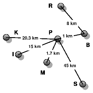 Figure 1: Overview of the WiLD campus testbed (not to scale)
We have implemented all our modifications as a shim layer above
the driver using the Click modular
router [11]. We have deployed WiLDNet in our campus
testbed of 6 long-distance wireless
links. Figure 1 shows the topology of our campus
testbed.
Apart from the design and implementation of WiLDNet, we have had two
years experience in deploying and maintaining two production WiLD
networks in India and Ghana that support real users. Our network at
the Aravind Eye Hospital, India, provides interactive patient-doctor
video-conferencing services between the hospital and five surrounding
villages (10-25 km away from the hospital). It is currently being
used for about 2000 remote patient examinations per month. The design
of WiLDNet that is presented in this paper has continuously evolved in
the past two years to solve many of the performance problems that we
faced in our deployments.
Using a detailed performance evaluation, we roughly observe a 2-5
fold improvement in the TCP throughput over WiLDNet in comparison to
the best achievable TCP throughput obtained by making minor driver
changes to the standard 802.11 MAC across a wide variety of
settings. On our outdoor testbed, we get upto 5 Mbps of TCP
throughput over 3 hops under lossy channel conditions,
which is 2.5 times more than that of standard 802.11b. The bandwidth
overhead of our loss-recovery mechanisms is minimal. In the near future
we intend to transition our system from the campus testbed into the two
production networks in India and Ghana.
Figure 1: Overview of the WiLD campus testbed (not to scale)
We have implemented all our modifications as a shim layer above
the driver using the Click modular
router [11]. We have deployed WiLDNet in our campus
testbed of 6 long-distance wireless
links. Figure 1 shows the topology of our campus
testbed.
Apart from the design and implementation of WiLDNet, we have had two
years experience in deploying and maintaining two production WiLD
networks in India and Ghana that support real users. Our network at
the Aravind Eye Hospital, India, provides interactive patient-doctor
video-conferencing services between the hospital and five surrounding
villages (10-25 km away from the hospital). It is currently being
used for about 2000 remote patient examinations per month. The design
of WiLDNet that is presented in this paper has continuously evolved in
the past two years to solve many of the performance problems that we
faced in our deployments.
Using a detailed performance evaluation, we roughly observe a 2-5
fold improvement in the TCP throughput over WiLDNet in comparison to
the best achievable TCP throughput obtained by making minor driver
changes to the standard 802.11 MAC across a wide variety of
settings. On our outdoor testbed, we get upto 5 Mbps of TCP
throughput over 3 hops under lossy channel conditions,
which is 2.5 times more than that of standard 802.11b. The bandwidth
overhead of our loss-recovery mechanisms is minimal. In the near future
we intend to transition our system from the campus testbed into the two
production networks in India and Ghana.
2 WiLD Performance Issues
In this section, we describe in detail two important causes for poor
end-to-end performance in WiLD networks: (a) 802.11 protocol
shortcomings; (b) high and variable loss-rates in the underlying
channel induced by external factors. We begin by providing a brief
description of WiLD networks in Section 2.1.
In Section 2.3, we elaborate on three protocol
shortcomings of 802.11 in WiLD settings: (a) inefficient link-level
recovery; (b) collisions at long distances and (c) inter-link interference.
For each of these, we show
that just manipulating driver level parameters is insufficient to
achieve good performance over long-distance links.
Then in Section 2.4, we summarize the results of
our study of the loss characteristics in our deployed WiLD networks.
We observed the primary cause of these losses to be
external WiFi interference and not multi-path effects.
Finally, in Section 2.5, we discuss the effect of these two
causes on TCP performance.
2.1 WiLD Networks: An Introduction
The IEEE 802.11 standard (WiFi) was designed for wireless broadcast
environments with many hosts in close vicinity competing for channel
access. Wireless radios are half-duplex and cannot listen while
transmitting; consequently, a CSMA/CA (carrier-sense
multiple-access/collision avoidance) mechanism is used to reduce
collisions. Unlike standard WiFi networks, WiFi-based Long Distance
(WiLD) networks use multi-hop point-to-point links, where each link can
be as long as 100 km. To achieve long distances in single
point-to-point links, nodes use directional antennas with gains as
high as 30dBi, and may use high-power wireless cards with up to
400mW of transmit power. Additionally, in multi-hop settings,
nodes have multiple radios with one radio per fixed point-to-point
link to each neighbor. Each radio can operate on different channels
if required. This is different from standard 802.11 networks where
nodes route traffic through an access point and contend for the
medium on a single channel. Some real life deployments of WiLD
networks include the Akshaya network [24], the Digital
Gangetic Plains project [4], and the CRCnet
project [8]. The Akshaya network is one of the largest
wireless deployments in the world with over 400 nodes and links going up to 30
km.
2.2 Experimental Setup
We use three different experimental setups to conduct measurements
and to evaluate WiLDNet.
Campus testbed: Figure 1 is
our real-world campus testbed on which we have currently deployed
WiLDNet. The campus testbed consists of links ranging from 1 to 45
km, with end points located in areas
with varying levels of external WiFi interference.
We also use one of the links in our Ghana network (65km).
Wireless Channel Emulator: The channel
emulator (Spirent 5500 [21]) enables repeatable experiments
by keeping the link conditions stable for the duration of the
experiment. Moreover, by introducing specific propagation delays we
can emulate very long links and hence study the
effect of long propagation delays. We can also study this in isolation of
external interference by placing the end host radios in RF isolation
boxes.
Indoor multi-hop testbed: We perform
controlled multi-hop experiments on an indoor multi-hop testbed
consisting of 4 nodes placed in RF isolated boxes.
The setup was designed to recreate conditions similar to long outdoor links
where transmissions from local radios interfere with each other but
simultaneous reception on multiple local radio interfaces is possible.
We can also control the amount of external interference
by placing an additional wireless node in each isolation box just to transmit
packets mimicking a real interferer. The amount of interference
is controlled by the rate of the CBR traffic sent by this node.
The indoor setup features very small propagation delay on the links;
we use it only to perform experiments evaluating TDMA scheduling
and loss recovery from interference.
We use Atheros 802.11 a/b/g radios for all our experiments. The
wireless nodes are 266 MHz x86 Geode single board computers running
Linux 2.4.26. The choice of this hardware platform is motivated
by the low cost ($140) and the low power consumption ( < 5W).
We use iperf to measure UDP and TCP throughput.
The madwifi Atheros driver was modified to collect relevant PHY and MAC layer
information.
2.3 802.11 Protocol Shortcomings
In this section, we study the three main limitations of the 802.11 protocol:
the inefficient link-layer recovery mechanism,
collisions in long-distance links,
and inter-link interference.
These limitations make 802.11 ill-suited even in the case of a single WiLD link. Based
on extensive experiments, we also show that modifying the driver-level
parameters of 802.11 is insufficient to achieve good performance.
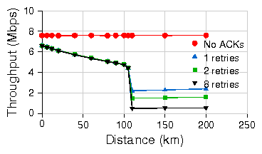
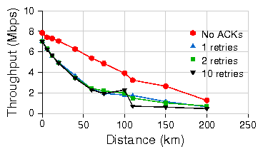
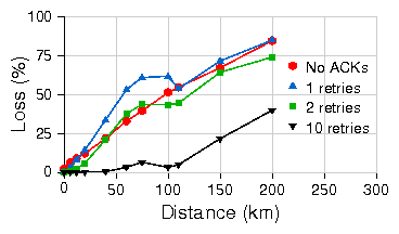 Figure 2: UDP throughputs for standard 802.11 CSMA on single emulated link.
ACK timeouts were adjusted with increasing distance (on Atheros cards).
Traffic is 1440 byte CBR UDP packets in 802.11b at PHY layer datarate of 11Mbps.
Figure 2: UDP throughputs for standard 802.11 CSMA on single emulated link.
ACK timeouts were adjusted with increasing distance (on Atheros cards).
Traffic is 1440 byte CBR UDP packets in 802.11b at PHY layer datarate of 11Mbps.
2.3.1 Inefficient Link-Layer Recovery
The 802.11 MAC uses a simple stop-and-wait protocol, with each packet
independently acknowledged. Upon successfully receiving a packet, the
receiver node is required to send an acknowledgment within a tight
time bound (ACKTimeout), or the sender has to retransmit. This
mechanism has two drawbacks:
�
As the link distance increases, propagation delay increases as well, and
the sender waits for a longer time for the ACK to return. This
decreases channel utilization.
�
If the time it takes for the ACK to return exceeds the ACKTimeout
parameter, the sender will retransmit unnecessarily and waste
bandwidth.
We illustrate these problems by performing experiments using the
wireless channel emulator. To emulate long distances, we configure the
emulator to introduce a delay to emulate links
ranging from 0-200 km.
Figure 2(a) shows the performance of the 802.11
stop-and-wait link recovery mechanism over increasing link distances.
With the MAC-layer ACKs turned off (No ACKs), we achieve a throughput
of 7.6 Mbps at the PHY layer data rate of 11 Mbps.
When MAC ACKs are enabled,
we adjust the ACK timeout as the distance increases.
In this case, the sender waits for an ACK after each transmission, and
we observe decreasing channel utilization as the propagation delay
increases. At 110 km, the propagation
delay exceeds the maximum ACK timeout (746ms for Atheros,
but smaller and fixed for Prism 2.5 chipsets)
and the sender always times out
before the ACKs can arrive. We notice a sharp decrease in received
throughput, as the sender retries to send the packet repeatedly (even
though the packets were most likely received), until the maximum
number of retries is reached (this happens because, if an ACK is late,
it is ignored). This causes the received throughput to
stabilize at BW110km/(no_of_retries + 1).
2.3.2 Collisions on long-distance links
The 802.11 protocol uses a CSMA/CA channel-access mechanism, in which nodes
listen to the medium for a specified time period (DIFS) before transmitting a
packet, thus ensuring that the channel is idle before transmission. This
translates to a maximum allowable distance at which collisions can be avoided
of about 15km for 802.11b (DIFS is 50ms), 10.2 kms for 802.11a and 8.4km
for 802.11g. For longer links it is possible for a node to start
transmitting a packet unaware of another packet transmission at the other end.
As the propagation delay increases, this probability of loss due to collisions
increases.
We illustrate the above-mentioned effect by using a simple experiment: we send
bidirectional UDP traffic at the maximum possible sending rate on the
emulated link and measure the percentage of packets successfully
received at each end. Figure 2(c) shows how the packet
loss rate increases with distance.
Figure 2(b) shows the sum of the throughputs achieved
at both ends for bidirectional UDP traffic as we increase the distance
for a link. Note that there are no losses due to attenuation or
outside interference in this controlled experiment; all of the losses
are due to collisions.
A possible solution to this issue would be to increase the DIFS time interval
in order to permit longer propagation delays. However, just as in the case
of the ACK timeout, this approach would decrease channel utilization
substantially for longer links. Furthermore, we are not aware of any
802.11 chipsets that allow the DIFS interval to be configured.
2.3.3 Multiple Link Interference
Another important source of errors is the interference between adjacent 802.11
links operating in the same channel or in overlapping channels. Although
interference between adjacent links can be avoided by using non-overlapping
channels, there are numerous reasons that make it advantageous to operate
adjacent links on the same frequency channel, as described by Raman et
al. [17]. Moreover, there are WiLD topologies such as the
Akshaya network [24] where different channels cannot be allocated to
all the pairs of adjacent links, given the high connectivity degree of several
nodes.
Inter-link interference occurs because the high-power radios create a strong RF
field in the vicinity of the radio, enough to interfere with the receptions at
nearby radios. Directional antennas also have sufficiently high gain (4-8 dBi)
side lobes [4] in addition to the main lobes.
The first type of problem occurs when multiple radios attached to the same node
attempt to transmit at the same time. As soon as one radio starts transmitting
after sensing the carrier to be idle, all other radios in the vicinity find the
carrier to be busy and backoff. This is desirable in a broadcast network to
avoid collisions between two senders at any receiver node. However, in our
network where each of these radios transmits over point-to-point long distance
links to independent receivers, this backoff leads to suboptimal throughput. A
second problem occurs when packets being received at one link collide with
packets simultaneously transmitted on some other link on the same node. The
signal strength of packets transmitted locally on a node overwhelms any packet
reception on other local radios.
In order to illustrate these effects, we perform experiments on the real-world
setup presented in Figure 1. First, we attempt to
simultaneously transmit UDP packets to both K and M from node P. The total
send throughput on both links is 14.20 Mbps when they are on non-overlapping
channels (separation � 4) but drops to only 7.88 Mbps when on the same
channel. Next we send UDP packets from node M to node K, relayed through node
P at different transmitting rates. We then measure received throughput and
packet loss rate for various channel spacing between the two adjacent links, as
presented in Figures 3(a) and
3(b). We observe that interference does reduce the
utilization of the individual links and significantly increases the link
loss rate (even in the case of partially overlapping channels).
Therefore, the maximum channel diversity that one can simultaneously use at a
single node in the case of 802.11(b) is restricted to 3 (channels 1,6,11) which
may not be sufficient for many WiLD networks. This motivates the need for a
scheme that allows the efficient operation of same-channel adjacent links. This
can be achieved by using a mechanism similar to the one used in 2P [17],
that synchronizes both packet transmission and reception across adjacent links to avoid
interference and improve throughput.
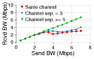
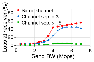 Figure 3: Effect of interference on received UDP throughput and
error rate when
sending from M to K through a relay node, P.
Channel separation is no. of channels in 802.11b.
Traffic is 1440 byte CBR UDP packets in 802.11b at PHY layer datarate of 11Mbps.
Figure 3: Effect of interference on received UDP throughput and
error rate when
sending from M to K through a relay node, P.
Channel separation is no. of channels in 802.11b.
Traffic is 1440 byte CBR UDP packets in 802.11b at PHY layer datarate of 11Mbps.
2.4 Channel Induced Loss
Apart from protocol shortcomings, another cause for poor performance
is high packet loss rates in the underlying channel due to external
factors. We refer to these as channel induced losses.
In this section, we briefly summarize the relevant conclusions
from our study (Sheth et al. [20])
where we conduct a detailed analysis of loss characterization
on our WiLD network deployments.
Loss magnitude and variability:
Figure 4 illustrates the loss variation across
time on two different links in our testbed.
We find that the loss is highly varying with time and there are
bursts of high loss of lengths varying from few milliseconds up to several minutes.
However on the urban links, there is always a non-zero residual
that varies between 1-20%.
The residual loss rates in our rural links are negligible.
Finally, we found the loss characteristics along a single
link to be highly asymmetric. One example is illustrated in
Figure 4 where we observe that average loss rate
from S to P was lower (10%) than the loss from P to S (20%).
Sources of loss:
Our study (Sheth et al. [20]) investigates two potential sources for
channel losses on WiLD links: external WiFi interference and multipath
interference. It finds external WiFi interference to be the dominant source of
packet loss and multipath to have a much smaller effect.
Multipath has a small effect because the delay spreads in WiLD
environments are an order of magnitude lower than those in mesh
networks. This is because as link distances increase, the
path delay difference between the primary line-of-sight (LOS) path and secondary
reflected paths becomes small enough to avoid inter-symbol interference (ISI).
On the other hand, the primary path signal can be significantly attenuated
from the secondary paths that undergo a phase shift of 180� after reflection.
This is verified by our measurements [20] where we see that
all our long-distance links in rural areas have very low loss.
In comparison, an urban mesh network deployment (like Roofnet)
has many short, non line-of-sight links and thus loss from ISI is a much bigger problem.
However if WiLD links are deployed in the presence of external interfering
sources, the hidden terminal problem can be much worse than in the case of an
urban mesh network (with omnidirectional antennas). Due to the highly
directional nature of the transmission, a larger fraction of interfering
sources within range of the receiver act as hidden terminals since they cannot
sense the sender's transmissions. In addition, due to long propagation delays,
even sources within the range of a directional transmitter
can interfere by detecting the conflict too late. Measurements on our outdoor
testbed links and indoor testbed demonstrate a strong correlation between loss
and volume of traffic from external sources on the same or adjacent
channels [20].
This is different from the case of WiFi mesh networks like
Roofnet [1], for which the authors concluded that
multipath interference was a significant source of packet loss, while
WiFi interference was not.
Other factors:
Measurements on our testbed show that there is no
measurable non-WiFi interference in our urban links [20]. This is
indicated by the absence of significant correlation between noise floor
(reported by the wireless card) and loss rates. Also, the loss rates on
different channels are not correlated to each other implying the absence of any
wide-band interfering noise. Experiments with different 802.11 PHY data rates
showed that smaller data rates can have higher loss rates in many situations.
This can be explained by the fact that packets at lower datarates take longer
time on air and are thus more likely to collide with external traffic.
Other studies by Raman et al. [7] show that weather
conditions don't have noticeable effects on loss rates in long distance links.
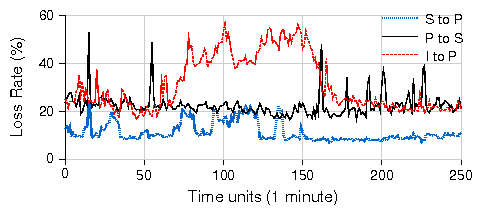 Figure 4: Packet loss variation on 2 links over a period of about 4 hours. Traffic was 1Mbps CBR UDP packets of 1440 bytes each at a PHY datarate of 11Mbps in 802.11b.
2.5 Impact on TCP
Taken together, the protocol shortcomings of 802.11 and channel induced
losses significantly lower end-to-end TCP performance. The use of
stop-and-wait over long distances reduces channel utilization. In
addition, we see correlated bursty collision losses due to interference from
unsynchronized transmissions (over both single-link and multi-hop
scenarios) as well as from external WiFi sources. Under
these conditions, TCP flows often timeout resulting in very poor
performance. The only configurable parameter in the
driver is the number of packet retries.
Setting a higher value
on the number of retries decreases the loss rate,
but at the cost of lower throughput resulting from lower channel utilization.
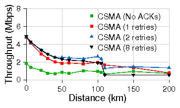 Figure 5: Cumulative throughput for TCP in both directions simultaneously
over standard CSMA with 10% channel loss on emulated link.
Traffic is 802.11b at PHY layer datarate of 11Mbps.
To better understand this trade-off, we measure
the aggregate throughput of TCP flows in both directions on an
emulated link while varying distance and
introducing a channel packet loss rate of 10%.
Figure 5 presents the aggregate
TCP throughput with various number of MAC retries of the standard 802.11 MAC.
Due to increased collisions and larger ACK turnaround times, throughput
degrades gradually with increasing distances.
Figure 5: Cumulative throughput for TCP in both directions simultaneously
over standard CSMA with 10% channel loss on emulated link.
Traffic is 802.11b at PHY layer datarate of 11Mbps.
To better understand this trade-off, we measure
the aggregate throughput of TCP flows in both directions on an
emulated link while varying distance and
introducing a channel packet loss rate of 10%.
Figure 5 presents the aggregate
TCP throughput with various number of MAC retries of the standard 802.11 MAC.
Due to increased collisions and larger ACK turnaround times, throughput
degrades gradually with increasing distances.
3 WiLDNet Design
In this section, we describe the design of WiLDNet and elaborate on how it
addresses the 802.11 protocol shortcomings as well as achieves good performance
in high-loss environments. In the previous section, we identified three basic
problems with 802.11; (a) low utilization, (b) collisions at long distances,
and (c) inter-link interference. To address the problem of low utilization, we
propose the use of bulk packet acknowledgments (Section 3.1).
To mitigate loss from collisions at long distances as well as
inter-link interference, we replace the standard CSMA MAC
with a TDMA-based MAC protocol.
We build upon 2P [17] to adapt it to high-loss environments
(Section 3.2).
Additionally, to handle the challenge of high and variable packet losses,
we design adaptive loss recovery mechanisms that use a
combination of FEC and retransmissions with bulk acknowledgments
(Section 3.3).
WiLDNet follows three main design principles. First, the system should not be
narrowly focused to a single set of application types. It should be
configurable to provide a broad tradeoff spectrum across different end-to-end
properties including delay, bandwidth, loss, reliability and jitter. Second, all
mechanisms proposed should be implementable on commodity off-the-shelf 802.11
cards. Third, the design should be lightweight, such that it can be
implemented on the resource-constrained single-board computers (266-MHz CPU and
128 MB memory) used in our testbed.
3.1 Bulk Acknowledgments
We begin with the simple case of a single WiLD link, with each node having a
half-duplex radio. As shown earlier, when propagation delays become
longer, the default CSMA mechanism cannot determine whether the remote peer
is sending a packet in time to back-off its own transmission and avoid collisions.
Moreover, such a contention-based mechanism is overkill
when precisely two hosts share the channel for a directional link.
Thus, a simple and efficient solution to avoid these collisions is to
use an echo protocol between the sender and the receiver, which allows the
two end-points to take turns sending and receiving packets.
Hence, from a node's perspective, we divide time into send and receive time
slots, with a burst of several packets being sent from one host to its peer in each slot.
Consequently, to improve link utilization, we replace the stock 802.11 stop-and-wait
protocol with a sliding-window based flow-control approach in which we
transmit a bulk acknowledgment (bulk ACK) from the receiver for a window of
packets. We generate a bulk ACK as an aggregated
acknowledgment for all the packets received within the previous
slot. In this way, a sender can rapidly transmit a burst of packets
rather than wait for an ACK after each packet.
The bulk ACK can be either piggybacked on data packets sent in the
reverse direction, or sent as one or more stand-alone packets if no data packets are ready. Each bulk ACK contains the sequence number of the last packet
received in order and a variable-length bit vector ACK for all packets
following the in-order sequence. Here, the sequence number of a packet is
locally defined between the pair of end-points of a WiLD link.
Like 802.11, the bulk ACK mechanism is not designed to
guarantee perfect reliability. 802.11 has a maximum number of retries
for every packet. Similarly, upon receiving a bulk ACK, the
sender can choose to advance the sliding window skipping
unacknowledged packets if the retry limit is exceeded.
In practice, we support different retry limits for packets of
different flows. The bulk ACK mechanism introduces packet reordering
at the link layer, which may not be acceptable for TCP traffic. To
handle this, we provide in-order packet delivery at the link layer
either for the entire link or at a per-flow basis.
3.2 Designing TDMA on Lossy Channels
To address the inappropriateness of CSMA for WiLD networks,
2P [17] proposes a contention-free TDMA based channel
access mechanism. 2P eliminates inter-link interference by
synchronizing all the packet transmissions at a given node (along all
links which operate on the same channel channel).
In 2P, a node in transmission mode simultaneously transmits on
all its links for a globally known specific period, and then
explicitly notifies the end of its transmission period to each of its
neighbors using marker packets. A receiving node waits for the marker
packets from all its neighbors before switching over to transmission
mode. In the event of a loss of a marker packet, a receiving node uses
a timeout to switch into the transmission mode.
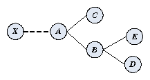 Figure 6: Example topology to compare synchronization of 2P and WiLDNet.
The design of 2P, while functional, is not well suited for lossy
environments. Consider the simple example illustrated in
Figure 6, where all links operate on the same channel.
Consider the case where (X,A) is the link
experiencing high packet loss-rate. Let T denote the value of the
time-slot. Whenever a marker packet transmitted by X is lost, A
begins transmission only after a timeout period T0 ( � T). This, in turn, delays the next set of transmissions from nodes
B and C to their other neighbors by a time period that equals T0-T. Unfortunately, this propagation of delay does not end here. In
the time slot that follows, D's transmission to its neighbors is
delayed by T0-T. Hence, what we observe is that the loss of marker
packets has a "ripple effect" in the entire network creating an idle
period of T0-T along every link. When markers along
different links are dropped, the ripples from multiple links can interact
with each other and cause more complex behavior.
Ideally, one would want T0 -T to be very small. If all nodes are
perfectly time synchronized, we can set T0=T. However, in the
absence of global time synchronization, one needs to set a
conservative value for T0. 2P chooses T0 = 1.25 ×T.
The loss of a marker packet leads to an idle period of 0.25 ×T
(in 2P, this is 5 ms for T=20 ms).
In bursty losses, transmitting multiple marker packets may not suffice.
Given that many of the links in our network experience sustained
loss-rates over 5-40%, in WiLDNet, we use an implicit
synchronization approach that aims to reduce the value of T0 -T.
In WiLDNet, we use a simple loose time synchronization mechanism
similar to the basic linear time synchronization protocol
NTP [13], where during each time slot along each link, the
sender acts as the master and the receiver as the slave. Consider a
link (A,B) where A is the sender and B is the receiver at a
given time. Let tsend_A and trecv_B denote the
start times of the slot as maintained by A and B.
All the packets sent by A are timestamped with the time
difference (d) between the time the packet has been sent
(t1) and the beginning of the send slot( tsend_A). When a
packet is received by B at time t2, the beginning of B's receiving
slot is adjusted accordingly: trecv_B = t2 - d.
As soon as B's receive slot is over, and
tsend_B = trecv_B + T is reached, B starts sending for a
period T.
Due to the propagation delay between A and B, the send and
corresponding receive slots are slightly skewed. The end-effect of
this loose synchronization is that the value of T0-T is limited by
the propagation delay across the link even with packet
losses (assuming clock speeds are roughly comparable). Hence, an
implicit synchronization approach significantly reduces the value of
T0 -T thereby reducing the overall number of idle periods in the network.
Figure 6: Example topology to compare synchronization of 2P and WiLDNet.
The design of 2P, while functional, is not well suited for lossy
environments. Consider the simple example illustrated in
Figure 6, where all links operate on the same channel.
Consider the case where (X,A) is the link
experiencing high packet loss-rate. Let T denote the value of the
time-slot. Whenever a marker packet transmitted by X is lost, A
begins transmission only after a timeout period T0 ( � T). This, in turn, delays the next set of transmissions from nodes
B and C to their other neighbors by a time period that equals T0-T. Unfortunately, this propagation of delay does not end here. In
the time slot that follows, D's transmission to its neighbors is
delayed by T0-T. Hence, what we observe is that the loss of marker
packets has a "ripple effect" in the entire network creating an idle
period of T0-T along every link. When markers along
different links are dropped, the ripples from multiple links can interact
with each other and cause more complex behavior.
Ideally, one would want T0 -T to be very small. If all nodes are
perfectly time synchronized, we can set T0=T. However, in the
absence of global time synchronization, one needs to set a
conservative value for T0. 2P chooses T0 = 1.25 ×T.
The loss of a marker packet leads to an idle period of 0.25 ×T
(in 2P, this is 5 ms for T=20 ms).
In bursty losses, transmitting multiple marker packets may not suffice.
Given that many of the links in our network experience sustained
loss-rates over 5-40%, in WiLDNet, we use an implicit
synchronization approach that aims to reduce the value of T0 -T.
In WiLDNet, we use a simple loose time synchronization mechanism
similar to the basic linear time synchronization protocol
NTP [13], where during each time slot along each link, the
sender acts as the master and the receiver as the slave. Consider a
link (A,B) where A is the sender and B is the receiver at a
given time. Let tsend_A and trecv_B denote the
start times of the slot as maintained by A and B.
All the packets sent by A are timestamped with the time
difference (d) between the time the packet has been sent
(t1) and the beginning of the send slot( tsend_A). When a
packet is received by B at time t2, the beginning of B's receiving
slot is adjusted accordingly: trecv_B = t2 - d.
As soon as B's receive slot is over, and
tsend_B = trecv_B + T is reached, B starts sending for a
period T.
Due to the propagation delay between A and B, the send and
corresponding receive slots are slightly skewed. The end-effect of
this loose synchronization is that the value of T0-T is limited by
the propagation delay across the link even with packet
losses (assuming clock speeds are roughly comparable). Hence, an
implicit synchronization approach significantly reduces the value of
T0 -T thereby reducing the overall number of idle periods in the network.
3.3 Adaptive Loss Recovery
To achieve predictable end-to-end performance, it is essential to have a
loss recovery mechanism that can hide the loss variability in the
underlying channel.
Achieving such an upper bound (q) on the loss-rate
perceived by higher level applications is not easy in our settings.
First, it is hard to predict the arrival and duration of bursts.
Second, the loss distribution that we observed on our links
is non-stationary even on
long time scales (hourly and daily basis). Hence,
a simple model cannot capture the channel loss characteristics.
In WiLDNet, we can either use retransmissions or FEC to deal with losses
(or a combination of both). A retransmission based approach can
achieve the loss-bound q with minimal throughput overhead but at the
expense of increased delay.
An FEC based approach incurs additional throughput overhead but does
not incur a delay penalty especially since it is used in combination
with TDMA on a per-slot basis.
However, an FEC approach cannot achieve arbitrarily low
loss-bounds mainly due to the unpredictability of the channel.
3.3.1 Tuning the Number of Retransmissions
To achieve a loss bound q independent of underlying channel loss
rate p(t), we need to tune the number of retransmissions. One can
adjust the number of retransmissions n(t) for a channel loss-rate
p(t) such that (1- p(t))n(t) = q. Given that our WiLD links
support in-order delivery (on a per-flow or on whole link basis),
a larger n(t) also means a larger maximum delay,
equal to n(t) * T for a slot period T. One can set different
values of n(t) for different flows. We found that estimating p(t)
using an exponentially weighted average is sufficient in our links to
achieve the target loss estimate q. A purely retransmission based
recovery mechanism has minimal throughput overhead as only the lost
packets are retransmitted but this comes at a cost of high delay due
to the long round-trip times over WiLD links.
3.3.2 Adaptive FEC-Based Recovery
Designing a good FEC mechanism in highly variable lossy conditions
requires accurate estimation of the underlying channel
loss. When the loss is underestimated, the redundant
packets cannot be decoded at all making them useless,
but overestimating the loss rate leads to unnecessary
overhead.
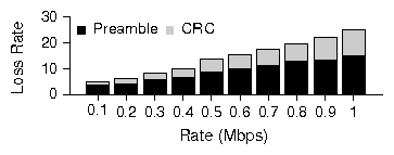 Figure 7: Proportion of CRC and preamble errors in channel loss.
Traffic is at UDP CBR packets of 1440 bytes each at 802.11b PHY datarate of 11Mbps. Main link is sending at 2Mbps. The sending rate of the interferer increases from 0.1Mbps to 1Mbps.
Motivating inter-packet FEC:
We can perform two types of FEC:
inter-packet FEC (coding across packets) or intra-packet FEC (coding
redundant blocks within a packet).
Based on extensive measurements on
a wireless channel emulator we observe that in presence of external
WiFi interference, lost packets can be categorized into either CRC
errors or preamble errors. A CRC error packet is received by the
driver with a check sum error. However, an error in the preamble leads
to the entire packet being dropped completely.
Figure 7 shows the breakup of
the loss rate with increasing external interference.
We observe although the proportion of preamble errors
decreases as external interference increases, it still
causes at least 50% of all errors. Moreover a substantial number
of the CRC error packets were truncated.
We choose not to perform intra-packet FEC because it can only help recover
packets that have CRC errors.
Hence, we chose to perform inter-packet FEC.
Estimating redundancy: We apply FEC in combination with TDMA. For every time slot of N
packets, we add N-K redundant packets to K original packets.
To estimate the redundancy factor, r = (N-K)/K,
we choose a simple but not perfect estimation policy based on a
weighted average of the losses observed in the previous M time
slots. Here, we specifically chose a small value of M=10
because it is hard to predict the start of a burst.
Secondly, a small value of M, can quickly
adapt to both the start and end of a loss burst
saving unnecessary redundant FEC packets.
For a time slot of T=10 ms, M=10 corresponds to
200 ms (with symmetric slot allocation in both directions)
to adapt to a change in the loss behavior.
Also due to non-stationary loss distributions,
the benefit of using more
complicated distribution based estimation approaches [22]
is marginal.
This type of FEC is best suited for handling residual losses and bursts
that are longer than the time required for loss estimation mechanism to adapt.
Figure 7: Proportion of CRC and preamble errors in channel loss.
Traffic is at UDP CBR packets of 1440 bytes each at 802.11b PHY datarate of 11Mbps. Main link is sending at 2Mbps. The sending rate of the interferer increases from 0.1Mbps to 1Mbps.
Motivating inter-packet FEC:
We can perform two types of FEC:
inter-packet FEC (coding across packets) or intra-packet FEC (coding
redundant blocks within a packet).
Based on extensive measurements on
a wireless channel emulator we observe that in presence of external
WiFi interference, lost packets can be categorized into either CRC
errors or preamble errors. A CRC error packet is received by the
driver with a check sum error. However, an error in the preamble leads
to the entire packet being dropped completely.
Figure 7 shows the breakup of
the loss rate with increasing external interference.
We observe although the proportion of preamble errors
decreases as external interference increases, it still
causes at least 50% of all errors. Moreover a substantial number
of the CRC error packets were truncated.
We choose not to perform intra-packet FEC because it can only help recover
packets that have CRC errors.
Hence, we chose to perform inter-packet FEC.
Estimating redundancy: We apply FEC in combination with TDMA. For every time slot of N
packets, we add N-K redundant packets to K original packets.
To estimate the redundancy factor, r = (N-K)/K,
we choose a simple but not perfect estimation policy based on a
weighted average of the losses observed in the previous M time
slots. Here, we specifically chose a small value of M=10
because it is hard to predict the start of a burst.
Secondly, a small value of M, can quickly
adapt to both the start and end of a loss burst
saving unnecessary redundant FEC packets.
For a time slot of T=10 ms, M=10 corresponds to
200 ms (with symmetric slot allocation in both directions)
to adapt to a change in the loss behavior.
Also due to non-stationary loss distributions,
the benefit of using more
complicated distribution based estimation approaches [22]
is marginal.
This type of FEC is best suited for handling residual losses and bursts
that are longer than the time required for loss estimation mechanism to adapt.
4 Implementation
In this section, we describe the implementation details of
WiLDNet. Our implementation comprises two parts: (a) driver-level
modifications to control or disable features implemented in hardware
(Section 4.1); (b) a shim layer that
sits above the 802.11 MAC (Section 4.2)
and uses the Click [11] modular router software to
implement the functionalities described in Section 3.
4.1 Driver Modifications
The wireless cards we use in our implementation are the high power
(200-400 mW) Atheros-based chipsets.
To implement WiLDNet, we have to disable the following 802.11 MAC mechanisms:
�We disable link-layer association
in Atheros chipsets using the AdHoc-demo mode.
�We disable link layer retransmissions and automatic ACKs
by using 802.11 QoS frames with WMM extensions set to the no-ACK policy.
�We disable CSMA by turning off the Clear Channel
Assessment (CCA) in Atheros chipsets.
With CCA turned off, the radio card can transmit packets right away without
waiting for a clear channel.
4.2 Software Architecture Modifications
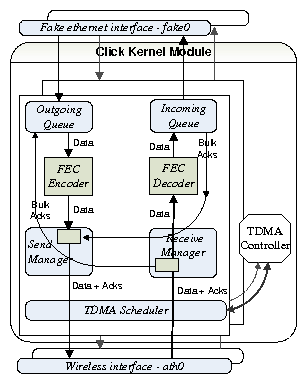 Figure 8: Click Module Data Flow
In order to implement single-link and inter-link synchronization using
TDMA, the various loss recovery mechanisms, sliding window flow control,
and packet reordering for in-order delivery, we use the Click modular
router [11] framework. We use Click because it
enables us to prototype quickly a modular MAC layer by composing different
Click elements together.
It is also reasonably efficient for packet
processing especially if loaded as a kernel module.
Using kernel taps, Click
creates fake network interfaces, such as fake0 in Figure 8
and the kernel communicates with these virtual interfaces.
Click allows us to intercept packets sent to this virtual interface
and modify them before sending them on the real wireless interface and vice versa.
Figure 8 presents the structure of the Click elements of our layered system,
with different functionality (and corresponding packet header processing) at various layers:
Incoming/Outgoing Queues: The mechanisms for sliding
window packet flow, bulk ACKs, selective retransmission and
reordering for in-order delivery are implemented by the incoming/outgoing queue
pair. Packet buffering at the sender is necessary for retransmissions, and
buffering at the receiver enables reordering.
In-order delivery and packet retransmission are
optional, and the number of retries can be set on a per-packet
basis.
FEC Encoder/Decoder: An optional layer is responsible for
inter-packet forward error correction encoding and decoding. For our
implementation we modify a FEC library [19] that uses erasure codes based on
Vandermonde matrices computed over GF(2m).
This FEC method uses a (K,N) scheme,
where the first K packets are sent in their
original form, and N-K redundant packets are generated,
for a total of N packets sent.
At the receiver, the reception of any K out of the N packets
enables the recovery of the original packets. We choose this scheme
because, in loss-less situations, it introduces very low
latency: the original K packets can be immediately sent by the encoder (without
undergoing encoding), and immediately delivered to the application by the decoder (without
undergoing decoding).
TDMA Scheduler and Controller:
The Scheduler ensures that packets are being
sent only during the designated send slots, and manages packet timestamps
as part of the synchronization mechanism.
The Controller implements synchronization
among the wireless radios, by enforcing synchronous
transmit and receive operation (all the
radios on the same channel have a common send slot, followed by a common
receive slot).
Figure 8: Click Module Data Flow
In order to implement single-link and inter-link synchronization using
TDMA, the various loss recovery mechanisms, sliding window flow control,
and packet reordering for in-order delivery, we use the Click modular
router [11] framework. We use Click because it
enables us to prototype quickly a modular MAC layer by composing different
Click elements together.
It is also reasonably efficient for packet
processing especially if loaded as a kernel module.
Using kernel taps, Click
creates fake network interfaces, such as fake0 in Figure 8
and the kernel communicates with these virtual interfaces.
Click allows us to intercept packets sent to this virtual interface
and modify them before sending them on the real wireless interface and vice versa.
Figure 8 presents the structure of the Click elements of our layered system,
with different functionality (and corresponding packet header processing) at various layers:
Incoming/Outgoing Queues: The mechanisms for sliding
window packet flow, bulk ACKs, selective retransmission and
reordering for in-order delivery are implemented by the incoming/outgoing queue
pair. Packet buffering at the sender is necessary for retransmissions, and
buffering at the receiver enables reordering.
In-order delivery and packet retransmission are
optional, and the number of retries can be set on a per-packet
basis.
FEC Encoder/Decoder: An optional layer is responsible for
inter-packet forward error correction encoding and decoding. For our
implementation we modify a FEC library [19] that uses erasure codes based on
Vandermonde matrices computed over GF(2m).
This FEC method uses a (K,N) scheme,
where the first K packets are sent in their
original form, and N-K redundant packets are generated,
for a total of N packets sent.
At the receiver, the reception of any K out of the N packets
enables the recovery of the original packets. We choose this scheme
because, in loss-less situations, it introduces very low
latency: the original K packets can be immediately sent by the encoder (without
undergoing encoding), and immediately delivered to the application by the decoder (without
undergoing decoding).
TDMA Scheduler and Controller:
The Scheduler ensures that packets are being
sent only during the designated send slots, and manages packet timestamps
as part of the synchronization mechanism.
The Controller implements synchronization
among the wireless radios, by enforcing synchronous
transmit and receive operation (all the
radios on the same channel have a common send slot, followed by a common
receive slot).
4.2.1 Timing issues
We do not use Click timers to implement time synchronization
because the underlying kernel timers are not precise at the granularity
of our time slots (10ms-40ms) on our hardware platform (266MHz CPU).
Also packet queuing in the wireless interface causes
variability in the time
between the moment Click emits a packet and the time the
packet is actually sent on the air interface. Thus, the propagation
delay between the sending and the receiving click modules on the two
hosts is not constant, affecting time slot calculations. Fortunately,
this propagation delay is predictable for the first packet in the send
slot, when the hardware interface queues are empty. Thus, in our
current implementation, we only timestamp the first packet in a slot,
and use it for adjusting the receive slot at the peer. If this packet
is lost, the receiver's slot is not adjusted in the current slot, but
since the drift is slow this does not have a significant impact.
In the future we intend to perform this timestamping
in the firmware - that would allow us to accurately timestamp every packet
just before packet transmission.
Another timing complication is related to estimating whether we have
time to send a new packet in the current send slot. Since the packets
are queued in the wireless interface, the time when the packet leaves Click
cannot be used to estimate this. To overcome this aspect, we use the
notion of virtual time. At the beginning of a send slot, the
virtual time tv is same as current (system) time tc.
Every time we send a packet, we
estimate the transmission time of the packet on the channel and
recompute the virtual time: tv = max(tc,tv) + duration(packet).
A packet is sent only after checking that the virtual time after
sending this packet will not exceed the end of the send slot.
Otherwise, we postpone the packet until the next slot.
5 Experimental Evaluation
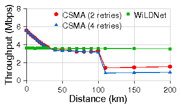
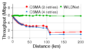
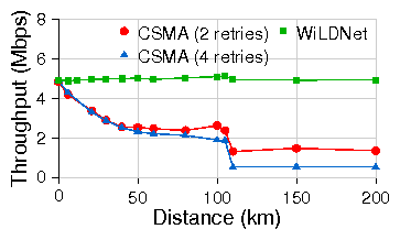 Figure 9: TCP throughput for WiLDNet vs 802.11 CSMA.
Each measurement is for a TCP flow of 60s, 802.11b PHY, 11Mbps.
Figure 9: TCP throughput for WiLDNet vs 802.11 CSMA.
Each measurement is for a TCP flow of 60s, 802.11b PHY, 11Mbps.
The main goals of WiLDNet are to increase link utilization and to
eliminate the various sources of packet loss observed in a typical
multi-hop WiLD deployment, while simultaneously providing flexibility
to meet different end-to-end application requirements.
We believe these are the first actual implementation results
over an outdoor multi-hop WiLD network deployment.
Raman et al. [17] show the improvements gained by
the 2P-MAC protocol in simulation and in an indoor environment.
However, a multi-hop outdoor deployment also has to deal with high losses
from external interference.
2P in its current form does not have any built-in recovery mechanism
and it is not clear how any recovery mechanism
can be combined with the marker-based synchronization protocol.
Hence, we do not have any direct comparison results with 2P on our
outdoor wireless links.
Also, the proof-of-concept implementation of 2P
was for the Prism 2.5 wireless chipset
and it would be non-trivial to implement the same
in WiLDNet using features of the Atheros chipset.
Our evaluation has three main parts:
� We analyze the ability of WiLDNet to
maintain high performance (high link utilization)
over long-distance WiLD links. At long
distances, we demonstrate 2-5x improvements in
cumulative throughput for TCP flows in both directions simultaneously.
� Next, we evaluate the ability of WiLDNet to scale
to multiple hops and eliminate inter-link interference. WiLDNet yields a
2.5x improvement in TCP throughput on our real-world
multi-hop setup.
� Finally, we evaluate the effectiveness of the two link recovery
mechanisms of WiLDNet: Bulk Acks and FEC.
5.1 Single Link
In this section we demonstrate the ability of WiLDNet to eliminate
link under-utilization and packet collisions over a single WiLD link.
We compare the performance of WiLDNet (slot size of 20ms)
with the standard 802.11 CSMA (2 retries) base case.
The first set of results show the improvement of WiLDNet on
a single emulator link with increasing distance.
Figure 9(a) compares the performance of TCP
flowing only in one direction. The lower throughput of
WiLDNet, approximately 50% of channel capacity, is due to symmetric
slot allocation between the two end points of the link. However, over
longer links ( > 50 km), the TDMA-based channel allocation avoids the
under-utilization of the link as experienced by CSMA.
Also, beyond 110 km (the maximum possible ACK timeout),
the throughput with CSMA drops rapidly because of
unnecessary retransmits (Section 2.3.1).
Figure 9(b) shows the cumulative throughput of TCP
flowing simultaneously in both directions. In this case, WiLDNet effectively
eliminates all collisions occurring in presence of bidirectional
traffic. TCP throughput of 6 Mbps is maintained for all distances.
Table 1 compares WiLDNet and CSMA for some of our
outdoor wireless links.
We show TCP throughput in one direction
and the cumulative throughput for TCP simultaneously flowing in both directions.
Since these are outdoor measurements, there is significant variation over time
and we show both the mean and standard deviation for the measurements.
We can see that as the link distance increases, the improvement of WiLDNet
is more substantial.
Infact, for the 65 km link in Ghana, WiLDNet's throughput at 5.5 Mbps is
about 8x better than standard CSMA.
| Link | Dist ance | Loss rates | 802.11 CSMA (Mbps) | WiLDNet (Mbps) |
| (km) | (%) | One dir | Both dir | One dir | Both dir | |
| B-R | 8 | 3.4 | 5.03 (0.02) | 4.95 (0.03) | 3.65 (0.01) | 5.86 (0.05) |
| P-S | 45 | 2.6 | 3.62 (0.20) | 3.52 (0.17) | 3.10 (0.05) | 4.91 (0.05) |
| Ghana | 65 | 1.0 | 2.80 (0.20) | 0.68 (0.39) | 2.98 (0.19) | 5.51 (0.07) |
Table 1: Mean TCP throughput
(flow in one direction and cumulative for both directions simultaneously)
for WiLDNet and CSMA for various outdoor links (distance and loss rates).
The standard deviation is shown in parenthesis for 10 measurements.
Each measurement is for TCP flow of 30s at a 802.11b PHY-layer datarate of 11Mbps.
5.2 Multiple Hops
This section validates that WiLDNet eliminates inter-link interference
by synchronizing receive and transmit slots in TDMA
resulting in up to 2x TCP throughput improvements over
standard 802.11 CSMA in multi-hop settings.
The first set of measurements were performed on our indoor setup
(Section 2.2) where we recreated the conditions of a linear outdoor
multi-hop topology using the RF isolation boxes.
Thus transmissions from local radios interfere with each other but
multiple local radio interfaces can receive simultaneously.
We then measure TCP throughput of flows in the one direction and
then both directions simultaneously for both standard 802.11 CSMA and WiLDNet
(with slot size of 20ms).
All the links were operating on the same channel.
As we see in Table 2, as the number of hops increases,
standard 802.11's TCP throughput drops substantially when
transmissions from a radio collide with packet reception on a nearby local
radio on the same node.
WiLDNet avoids these collisions and maintains a much higher
cumulative TCP throughput (up to 2x for the 3-hop setup)
by proper synchronization of send and receive slots.
We can also see that although WiLDNet has more than 2x improvement over
standard 802.11, the final throughput (4.6Mbps)
is still much smaller than the raw
throughput of the link (6-7Mbps). This can be attributed to the overhead of
synchronization and packet processing in Click running
on our low-power (266MHz) single board routers.
A more efficient synchronization
mechanism implemented in the firmware (rather than Click) would deliver much
better improvement.
| Linear setup | 802.11 CSMA (Mbps) | WiLDNet (Mbps) |
| Dir 1 | Dir 2 | Both | Dir 1 | Dir 2 | Both | |
| 2 nodes | 5.74 (0.01) | 5.74 (0.01) | 6.00 (0.01) | 3.56 (0.03) | 3.53 (0.02) | 5.85 (0.07) |
| 3 nodes | 2.60 (0.01) | 2.48 (0.01) | 2.62 (0.01) | 3.12 (0.01) | 3.12 (0.01) | 5.12 (0.03) |
| 4 nodes | 2.23 (0.01) | 2.10 (0.01) | 1.99 (0.02) | 2.95 (0.05) | 2.98 (0.04) | 4.64 (0.24) |
Table 2:
Mean TCP throughput (flow in each direction and cumulative for both directions simultaneously)
for WiLDNet and standard 802.11 CSMA.
Measurements are for linear 2,3 and 4 node indoor setups recreating outdoor links running
on the same channel.
The standard deviation is shown in parenthesis for 10 measurements of
flow of 60s each at 802.11b PHY layer datarate of 11Mbps.
| Description (Mbps) | One | Both |
| direction | directions |
| Standard TCP: same channel | 2.17 | 2.11 |
| Standard TCP: diff channels | 3.95 | 4.50 |
| WiLD TCP: same channel | 3.12 | 4.86 |
| WiLD TCP: diff channels | 3.14 | 4 |
Table 3: Mean TCP throughput
(flow in single direction and cumulative for both directions simultaneously)
comparison for WiLDNet and
standard 802.11 CSMA over a 3-hop outdoor setup (K� P� M).
Averaged over 10 measurements of TCP flow for 60s at
802.11b PHY layer datarate of 11Mbps.
We also measure this improvement on our outdoor testbed between
the nodes K and M relayed through node P.
We again compare the TCP throughput for WiLDNet and standard 802.11 CSMA
with links operating on the same channel.
In order to quantify the effect of inter-link interference,
we also perform the same experiments with the
links operating on different, non-overlapping channels, in which case
the inter-link interference is almost zero, as previously shown in
Figure 3.
We can see that, for same channel operation, the
cumulative TCP throughput in both directions with WiLDNet (4.86 Mbps)
is more than twice the throughput
observed over standard 802.11 (2.11 Mbps). The improvement is
substantially lower for the unidirectional case (3.14 Mbps versus 2.17
Mbps), because the WiLD links are constrained to send in one direction
only roughly half of the time.
Another key observation is that WiLDNet is capable of
eliminating almost all inter-link interference. This is shown by the
fact that the throughput achieved by WiLDNet is almost the same,
whether the links operate on the same channel or on non-overlapping
channels.
| |
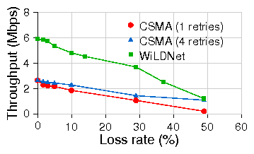 Figure 10:
Comparison of cumulative throughput for TCP in both directions simultaneously
for WiLDNet and standard 802.11 CSMA with increasing loss on 80km emulated link.
Each measurement was for 60s TCP flows of 802.11b at 11Mbps PHY datarate.
Figure 10:
Comparison of cumulative throughput for TCP in both directions simultaneously
for WiLDNet and standard 802.11 CSMA with increasing loss on 80km emulated link.
Each measurement was for 60s TCP flows of 802.11b at 11Mbps PHY datarate.
|
| |
| |
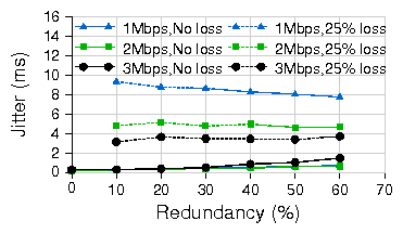 Figure 11: Jitter overhead of encoding and decoding for WiLDNet on single indoor link.
Traffic is 1440 byte UDP CBR packets at PHY datarate of 11Mbps in 802.11b.
Figure 11: Jitter overhead of encoding and decoding for WiLDNet on single indoor link.
Traffic is 1440 byte UDP CBR packets at PHY datarate of 11Mbps in 802.11b.
|
| |
| |
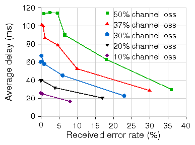 Figure 12: Avg. delay with decreasing target loss rate (X-axis) for
various loss rates in WiLDNet on single emulated 60km link (slot size=20ms).
Figure 12: Avg. delay with decreasing target loss rate (X-axis) for
various loss rates in WiLDNet on single emulated 60km link (slot size=20ms).
|
| |
| |
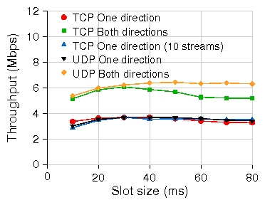 Figure 13: Throughput for increasing slot sizes (X-axis) in WiLDNet for various types of traffic on single emulated 60km link.
|
| |
| |
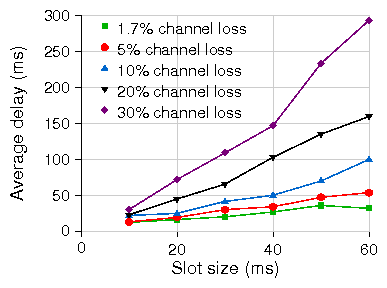 Figure 14: Avg. delay at increasing slot sizes (X-axis) for various loss rates in WiLDNet on single emulated 60km link.
|
| |
5.3 WiLDNet Link-Recovery Mechanisms
Our next set of experiments evaluate WiLDNet's adaptive link recovery
mechanisms in conditions closer to the real world, where errors are
generated by a combination of collisions and external interference. We
evaluate both the bulk ACK and FEC recovery mechanisms.
5.3.1 Bulk ACK Recovery Mechanism
For our first experiment, presented in
Figure 9(c), we vary the
link length on the emulator, and we introduce a 10% error rate through external
interference. We again measure
the cumulative throughput of TCP flows in both directions
for WiLDNet and standard 802.11 CSMA.
As can be seen, WiLDNet maintains a constant throughput with increasing
distance as opposed to the 802.11 CSMA.
Due to the 10% error, WiLD incurs a constant throughput penalty
of approximately 1 Mbps compared to the no-loss case
in Figure 9(b).
In our second experiment we fix the distance in the emulator setup to 80 km, and
vary channel loss rates. The results in
Figure 10 show that WiLDNet maintains roughly a
2x improvement over standard CSMA's recovery mechanism
for packet loss rates up to 30%.
5.3.2 Forward Error Correction (FEC)
To measure the jitter introduced by the FEC mechanism,
we performed a simple experiment where we measured the jitter of a flow
under two conditions: in the absence of any loss and in the
presence of a 25% loss. Figure 11 illustrates the
jitter introduced by WiLDNet's FEC implementation. We can see that in the
absence of any loss, when only encoding occurs, the jitter is
minimal. However, in the presence of loss, when decoding also takes
place, the measured jitter increases. However, the magnitude of the
jitter is very small and well within the acceptable limits of many
interactive applications (voice or video), and decreases with higher throughputs
(since the decoder waits less for redundant packets to arrive).
Moreover, considering the combination of FEC with TDMA, the delay overheads
introduced by these methods overlap, since the slots when
the host is not actively sending can be used to perform encoding without
incurring any additional delay penalties.
6 Tradeoffs
One of the main design principles of WiLDNet is to build a
system that can be configured to adapt to different application
requirements. In this section we explore the tradeoff space of
throughput, delay and delivered error rates by varying the slot size,
number of bulk retransmissions and FEC redundancy parameters. We
observe that WiLDNet can perform in a wide spectrum of the parameter
space, and can easily be configured to meet specific application
requirements.
6.1 Choosing number of retransmissions
The first tradeoff that we explore is choosing the number of retries
to get a desired level of final error rate on a WiLD link. Although
retransmission based loss recovery achieves optimal throughput
utilization, it comes at a cost of increased delay; the loss rate can
be reduced to zero by arbitrarily increasing the number of
retransmissions at the cost of increased delay. This tradeoff is
illustrated in Figure 12 which shows a plot of
delay versus error rate for varying channel loss rates (10% to
50%). Retries are decreased from 10 to 0
from left to right for a given series in the figure.
All the tests are with unidirectional UDP at 1 Mbps for a
fixed slot size of 20ms on a single emulator 60km link.
We can see that as we try to reduce the
final error rate at the receiver, we have to use more retries and this
increases the average delay. In addition, we also observe that
larger the number of retries, larger the end-to-end jitter (especially
at higher loss rates).
This tradeoff has important implications for applications that are
more sensitive to delay and jitter (such as real time audio and video)
as compared to applications which require high reliability. For such
applications, we can achieve a balance between the final error rate
and the average delay by choosing an appropriate retry limit. For
applications that require improved loss characteristics without
incurring a delay penalty, we need to use FEC for loss recovery.
6.2 Choosing slot size
The second tradeoff that we explore is the effect of slot
size on TCP and UDP throughput .
Our experiments are performed on a 60-km emulated link (Figure 13).
As discussed in
Section 3.2, switching between send and receive slots
incurs a non-negligible overhead for the
Click based WiLDNet implementation. This overhead
although constant for all slot sizes, occupies a higher fraction
of the slot for smaller slots sizes.
As a consequence, at small
slot sizes the achieved throughput is lower.
However, the UDP throughput levels off beyond a slot size of 20 ms. We also observe the
TCP throughput reducing slightly at higher slot size. This is because
the bandwidth-delay product of the link increases with slot size, but
the send TCP window sizes are fixed. UDP throughput does not decrease
at higher slot sizes.
In the next experiment, we measure the average UDP packet transmission
delay while varying the slot size, for several channel error
rates. The results are presented in Figure 14; each
series represents a unidirectional UDP test (1 Mbps CBR)
at a particular channel loss rate with WiLDNet using
maximum number of retries.
Figure 14 shows the
increase in delay with increasing slot size. It is clear that slot
sizes beyond 20 ms do not result in substantially higher throughputs,
but they do result in much larger delay.
However, if lower delay is required, smaller slots can be used at the expense
of some throughput overhead consumed by the switching between the
transmit and receive modes.
6.3 Choosing FEC parameters
The primary tunable FEC parameter is the redundancy factor
r = (N-K)/K, also referred to as throughput overhead. Although FEC
incurs a higher throughput overhead than retransmissions, it incurs a
smaller delay penalty as illustrated earlier in
Section 5.3.2. To analyze the tradeoff between
FEC throughput overhead and the target loss-rate, we consider the case
of a single WiLD link (in our emulator environment) with a simple
Bernoulli loss-model (every packet is dropped with probability
p).
Figure 15 shows the amount of redundancy
required to meet three different target loss-rates of 10%, 5% or 1%
as the raw channel error rates (namely p) increase.
We see that in order to achieve very low target loss-rates,
a lot of redundancy is required (for example, FEC incurs a 100%
overhead to reduce the loss-rate from 30% to 1%).
Also, when a channel is very bursty and has an unpredictable burst
arrival pattern, it is very hard for FEC to achieve arbitrarily low
target loss-rates.
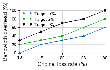 Figure 15: Throughput overhead vs channel loss rate for FEC on single emulated 20km link. Traffic is 1Mbps CBR UDP.
For applications that can tolerate one round of
retransmissions, we can use a combination of FEC and
retransmissions to provide a tradeoff between overall throughput
overhead, delay and target loss-rate. In the case of a channel with a
stationary loss distribution, OverQoS [22] shows that the
optimal policy to minimize overhead is to not use FEC in the first
round but use it in the second round to pad retransmission packets.
With unpredictable and highly varying channel loss conditions,
an alternative promising strategy is to use FEC in the first round
during bursty periods to reduce the perceived loss-rate.
Figure 15: Throughput overhead vs channel loss rate for FEC on single emulated 20km link. Traffic is 1Mbps CBR UDP.
For applications that can tolerate one round of
retransmissions, we can use a combination of FEC and
retransmissions to provide a tradeoff between overall throughput
overhead, delay and target loss-rate. In the case of a channel with a
stationary loss distribution, OverQoS [22] shows that the
optimal policy to minimize overhead is to not use FEC in the first
round but use it in the second round to pad retransmission packets.
With unpredictable and highly varying channel loss conditions,
an alternative promising strategy is to use FEC in the first round
during bursty periods to reduce the perceived loss-rate.
7 Related Work
Long Distance WiFi: The use of 802.11 for long distance
networking with directional links and multiple radios per
node, raises a new set of technical issues that were first illustrated
in [4]. Raman et al.built upon this work in
[17,16] and proposed the 2P MAC
protocol. WiLDNet builds upon 2P to make it robust in high
loss environments.
Specifically we modify 2P's implicit
synchronization mechanism as well as build in adaptive bulk
ACK based and FEC based link recovery mechanisms.
Other wireless loss recovery mechanisms: There is a large body of research
literature in wireless and wireline networks that have studied the
tradeoffs between different forms of loss recovery mechanisms.
Many of the classic error control mechanisms are
summarized in the book by Lin and Costello [12].
OverQoS [22] performs recovery by analyzing the FEC/ARQ tradeoff
in variable channel conditions and
the Vandermonde codes are used for reliable multicast in wireless
environments [19].
Of particular interest for this work are the Berkeley Snoop protocol
[2] which provides transport-aware link-layer
recovery mechanisms in wireless environments.
To compare the WiLDNet bulk ACK recovery mechanism with recovery at a higher
layer, we experimented with a version of the original Snoop
protocol [3] that we modified to run on
WiLD links. Basically, each WiLD router ran one half of Snoop, the
fixed host to mobile host part, for each each outgoing link and
integrated all the Snoops on different links into one module.
We measured the performance of modified Snoop as a recovery mechanism
over both standard 802.11 (CSMA) and over WiLDNet with no
retries. We found that WiLDNet was still 2x better than Snoop.
We also saw that Snoop was better than
vanilla CSMA only at lower error rates (less than 10%).
Thus, this indicates that higher layer recovery mechanisms might be better than stock 802.11
protocol, but only at lower error rates.
Other WiFi-based MAC protocols: Several recent efforts have focused on
leveraging off-the-shelf 802.11 hardware to design new MAC protocols.
Overlay MAC Layer (OML) [18]
provides a deployable approach towards implementing a TDMA style MAC
on top of the 802.11 MAC using loosely-synchronized clocks to provide
applications and competing nodes better control over the allocation of
time-slots. SoftMAC [14] is another platform to
build experimental MAC protocols.
MultiMAC [10] builds on SoftMac to provide a
platform where multiple MAC layers co-exist in the network
stack and any one can be chosen on a per-packet basis.
WiMax: An alternative to WiLD networks is WiMax [25].
WiMax does present many strengths over a WiFi: configurable channel
spectrum width, better modulation (especially
for non-line of sight scenarios), operation in licensed spectrum with
higher transmit power, and thus longer distances.
On the other hand, WiMax currently is primarily intended for
carriers (like cellular) and does not
support point-to-point operation.
In addition, WiMax base-stations are expensive ($10,000)
and the high spectrum license costs in most countries
dissuades grassroots style deployments.
Currently it is also very difficult to obtain licenses
for experimental deployment and we are not aware of open-source
drivers for WiMax base-stations and clients.
However, most of our work in loss recovery and adaptive FEC would
be equally valid for any PHY layer (WiFi or WiMax).
With appropriate modifications and cost reductions, WiMax can serve as a more
suitable PHY layer for WiLD networks.
8 Future Work and Conclusion
The commoditization of WiFi (802.11 MAC) hardware has made WiLD
networks an extremely cost-effective option for providing network
connectivity, especially in rural regions in developing countries.
However providing coverage at high performance in
real-world WiLD network deployments raises many research challenges:
optimal planning and placement of long distance links,
design of appropriate MAC and network protocols to provide quality of service
to a wide variety of applications,
remote management and fault tolerance to handle
unpredictable node and link failures [23].
One of the most important challenges in this space
is the sub-optimal performance of the standard 802.11 MAC protocol.
In this paper, we identify
the set of link- and MAC-layer modifications essential for achieving high
throughput in multi-hop WiLD networks. Specifically, using a
detailed performance evaluation, we show that the conventional 802.11
protocol is ill-suited for WiLD settings. Our proposed solution
provides a 2-5x improvement in TCP throughput over the conventional
802.11 MAC.
Although this constitutes a substantial improvement,
designing decentralized TDMA slot scheduling schemes for multi-hop and multi-channel networks
to achieve optimal bandwidth and delay characteristics for
realistic real-world asymmetric traffic demands is a significant future research direction.
Our current solution builds the basic link mechanisms to provide quality of service.
We intend to build end-to-end QoS solutions that leverage these mechanisms
and adapt to a realistic traffic mix.
Encouraged by our initial results on our long
distance outdoor testbed, we will now implement these modifications in
our live rural deployments in India and Ghana.
We expect that these improvements can have significant impact in accelerating the
penetration of feasible network connectivity options in developing regions.
Acknowledgments
We thank the whole TIER group at UC Berkeley and Intel Research,
Berkeley for braving wind, sun, rain and crazy taxi drivers to set up long-distance links
in India, Ghana and the Bay Area so that we can run our experiments.
We thank all the anonymous reviewers for their feedback and
owe our gratitude to Brad Karp, our NSDI shepherd for his valuable comments which
helped in substantially improving the paper.
References
- [1]
-
D. Aguayo, J. Bicket, S. Biswas, G. Judd, and R. Morris.
Link-level Measurements from an 802.11b Mesh Network.
In ACM SIGCOMM, Aug. 2004.
- [2]
-
H. Balakrishan.
Challenges to Reliable Data Transport over Heterogeneous
Wireless Networks.
PhD thesis, University of California at Berkeley, Aug. 1998.
- [3]
-
H. Balakrishnan, S. Seshan, E. Amir, and R. Katz.
Improving TCP/IP Performance over Wireless Networks.
In ACM MOBICOM, Nov. 1995.
- [4]
-
P. Bhagwat, B. Raman, and D. Sanghi.
Turning 802.11 Inside-out.
ACM SIGCOMM CCR, 2004.
- [5]
-
S. Biswas and R. Morris.
Opportunistic Routing in Multi-Hop Wireless Networks.
Hotnets-II, November 2003.
- [6]
-
E. Brewer.
Technology Insights for Rural Connectivity.
Oct. 2005.
- [7]
-
K. Chebrolu, B. Raman, and S. Sen.
Long-Distance 802.11b Links: Performance Measurements and
Experience.
In ACM MOBICOM, 2006.
- [8]
-
Connecting Rural Communities with WiFi.
http://www.crc.net.nz.
- [9]
-
Digital Gangetic Plains.
http://www.iitk.ac.in/mladgp/.
- [10]
-
C. Doerr, M. Neufeld, J. Filfield, T. Weingart, D. C. Sicker, and D. Grunwald.
MultiMAC - An Adaptive MAC Framework for Dynamic Radio Networking.
In IEEE DySPAN, Nov. 2005.
- [11]
-
E. Kohler, R. Morris, B. Chen, J. Jannotti, and M. F. Kaashoek.
The Click Modular Router.
ACM Transactions on Computer Systems, 18(3):263-297, Aug.
2000.
- [12]
-
S. Lin and D. Costello.
Error Control Coding: Fundamentals and Applications.
Prentice Hall, 1983.
- [13]
-
D. L. Mills.
Internet Time Synchronization: The Network Time Protocol.
In Global States and Time in Distributed Systems, IEEE Computer
Society Press. 1994.
- [14]
-
M. Neufeld, J. Fifield, C. Doerr, A. Sheth, and D. Grunwald.
SoftMAC - Flexible Wireless Research Platform.
In HotNets-IV, Nov. 2005.
- [15]
-
Partnership for Higher Education in Africa.
Securing the Linchpin: More Bandwidth at Lower Cost, 2006.
- [16]
-
B. Raman and K. Chebrolu.
Revisiting MAC Design for an 802.11-based Mesh Network.
In HotNets-III, 2004.
- [17]
-
B. Raman and K. Chebrolu.
Design and Evaluation of a new MAC Protocol for Long-Distance 802.11
Mesh Networks.
In ACM MOBICOM, Aug. 2005.
- [18]
-
A. Rao and I. Stoica.
An Overlay MAC layer for 802.11 Networks.
In MOBISYS, Seattle,WA, USA, June 2005.
- [19]
-
L. Rizzo.
Effective Erasure codes for Reliable Computer Communication
Protocols.
ACM CCR, 1997.
- [20]
-
A. Sheth, S. Nedevschi, R. Patra, S. Surana, L. Subramanian, and E. Brewer.
Packet Loss Characterization in WiFi-based Long Distance Networks.
IEEE INFOCOM, 2007.
- [21]
-
Spirent Communications.
http://www.spirentcom.com.
- [22]
-
L. Subramanian, I. Stoica, H. Balakrishnan, and R. Katz.
OverQoS: An Overlay Based Architecture for Enhancing Internet QoS.
In USENIX/ACM NSDI, March 2004.
- [23]
-
L. Subramanian, S. Surana, R. Patra, M. Ho, A. Sheth, and E. Brewer.
Rethinking Wireless for the Developing World.
Hotnets-V, 2006.
- [24]
-
The Akshaya E-Literacy Project.
http://www.akshaya.net.
- [25]
-
WiMAX forum.
http://www.wimaxforum.org.
Footnotes:
1This work was partly supported by National Science Foundation grant No. 0326582 and Intel Research.
2University of California, Berkeley
3Intel Research, Berkeley
4University of Colorado, Boulder
5New York University
|