Measurement and Analysis of TCP Throughput Collapse in Cluster-based Storage SystemsAmar Phanishayee, Elie Krevat, Vijay
Vasudevan,
|
Cluster-based and iSCSI-based storage systems rely on standard TCP/IP-over-Ethernet for client access to data. Unfortunately, when data is striped over multiple networked storage nodes, a client can experience a TCP throughput collapse that results in much lower read bandwidth than should be provided by the available network links. Conceptually, this problem arises because the client simultaneously reads fragments of a data block from multiple sources that together send enough data to overload the switch buffers on the client's link. This paper analyzes this Incast problem, explores its sensitivity to various system parameters, and examines the effectiveness of alternative TCP- and Ethernet-level strategies in mitigating the TCP throughput collapse.
Cluster-based storage systems are becoming an increasingly important target for both research and industry [1, 36, 15, 24, 14, 8]. These storage systems consist of a networked set of smaller storage servers, with data spread across these servers to increase performance and reliability. Building these systems using commodity TCP/IP and Ethernet networks is attractive because of their low cost and ease-of-use, and because of the desire to share the bandwidth of a storage cluster over multiple compute clusters, visualization systems, and personal machines. Furthermore, non-IP storage networking lacks some of the mature capabilities and breadth of services available in IP networks. However, building storage systems on TCP/IP and Ethernet poses several challenges. In this paper, we analyze one important barrier to high-performance storage over TCP/IP: the Incast problem [24].1
Incast is a catastrophic TCP throughput collapse that occurs as the number of storage servers sending data to a client increases past the ability of an Ethernet switch to buffer packets. As we explore further in §2, the problem arises from a subtle interaction between limited Ethernet switch buffer sizes, the communication patterns common in cluster-based storage systems, and TCP's loss recovery mechanisms. Briefly put, data striping couples the behavior of multiple storage servers, so the system is limited by the request completion time of the slowest storage node [7]. Small Ethernet buffers are exhausted by a concurrent flood of traffic from many servers, which results in packet loss and one or more TCP timeouts. These timeouts impose a delay of hundreds of milliseconds–orders of magnitude greater than typical data fetch times–significantly degrading overall throughput.
This paper provides three contributions. First, we explore in detail the root causes of the Incast problem, characterizing its behavior under a variety of conditions (buffer space, varying numbers of servers, etc.). We find that Incast is a general barrier to increasing the number of source nodes in a cluster-based storage system. While increasing the amount of buffer space available can delay the onset of Incast, any particular switch configuration will have some maximum number of servers that can send simultaneously before throughput collapse occurs.
Second, we examine the effectiveness of existing TCP variants (e.g., Reno [3], NewReno [13], SACK [22], and limited transmit [2]) designed to improve the robustness of TCP's loss recovery. While we do find that the move from Reno to NewReno substantially improves performance, none of the additional improvements help. Fundamentally, when TCP loses all packets in its window or loses retransmissions, no clever loss recovery algorithms can help.
Third, we examine a set of techniques that are moderately effective in masking Incast, such as drastically reducing TCP's retransmission timeout timer. With some of these solutions, building a high-performance, scalable cluster storage system atop TCP/IP and Ethernet can be practical. Unfortunately, while these techniques can be effective, none of them is without drawbacks. Our final conclusion is that no existing solutions are entirely sufficient, and further research is clearly indicated to devise a principled solution for the Incast problem.
In cluster-based storage systems, data is stored across many storage servers to improve both reliability and performance. Typically, their networks have high bandwidth (1-10 Gbps) and low latency (round trip times of tens to hundreds of microseconds) with clients separated from storage servers by one or more switches.
In this environment, data blocks are striped over a number of servers, such that each server stores a fragment of a data block, denoted as a Server Request Unit (SRU), as shown in Figure 1. A client requesting a data block sends request packets to all of the storage servers containing data for that particular block; the client requests the next block only after it has received all the data for the current block. We refer to such reads as synchronized reads.
This simple environment abstracts away many details of real storage systems, such as multiple stripes per data block, multiple outstanding block requests from a client, and multiple clients on a single switch making requests across a shared subset of servers. However, this is the most basic representative setting in which Incast can occur and simplifies our analysis.
The need for a high performance environment that supports parallel operations such as synchronized reads is particularly important because of such recent projects as Parallel NFS (pNFS). pNFS is a component of NFSv4.1 that supports parallel data transfers and data striping across multiple file servers [37, 28, 18].
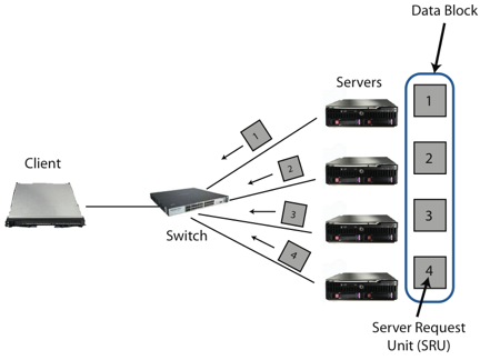
Figure 1: A simple cluster-based storage environment with one client requesting data from multiple servers through synchronized reads.
Most networks are provisioned so the client's link capacity to the switch is the throughput bottleneck of any parallel data transfer [16, 21]. Unfortunately, when performing synchronized reads for data blocks across an increasing number of servers, a client may observe a TCP throughput drop of one or two orders of magnitude below its link capacity. Figure 2 illustrates this performance drop in a cluster-based storage network environment when a client requests data from just seven servers.
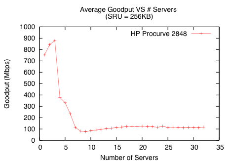
Figure 2: TCP throughput collapse for a synchronized reads application performed on a storage cluster.
Early parallel network storage projects, such as the NASD project [15], observed TCP throughput collapse in cluster-based storage systems during synchronous data transfers. This was documented as part of a larger paper by Nagle et al. [24], who termed the problem Incast and attributed it to multiple senders overwhelming a fixed-size switch buffer. However, while Nagle demonstrated the problem and suggested that an alternative TCP implementation shows a modest improvement, a full analysis and measurement of the problem was not performed nor were possible solutions presented.
Incast has not been thoroughly studied. Current systems attempt to avoid TCP throughput collapse by limiting the number of servers involved in any block transfer, or by artificially limiting the rate at which they transfer data. These solutions, however, are typically specific to one configuration (e.g. a number of servers, data block sizes, link capacities, etc.), and thus are not robust to changes in the storage network environment.
In this section, we describe the simulation and real system environments where we measure the effects of Incast and the corresponding workloads that we use in both settings.
All of our simulations use ns-2 [27], an event-driven network simulator that models networked applications at the packet granularity. Our default simulation configuration consists of one client and multiple servers all connected to the same switch as shown in Figure 1.
Table 1 shows the parameters and their corresponding default values that we vary in simulation. We choose a 256KB default SRU size to model a production storage system [9]. From our simulations, we obtain global and per-flow TCP statistics such as retransmission events, timeout events, TCP window sizes, and other TCP parameters to aid in our analysis of Incast.
Parameter Default Number of servers — SRU Size 256KB Link Bandwidth 1 Gbps Round Trip Time (RTT) 100µs Per-port switch output buffer size — TCP Implementation: Reno, NewReno, SACK NewReno Limited Transmit disabled Duplicate-ACK threshold (dathresh) 3 Slow Start enabled RTOmin 200ms
Our test application performs synchronized reads over TCP in ns-2 to model a typical striped file system data transfer operation. The client requests a data block from n servers by sending a request packet to each server for one SRU worth of data. When a client receives the entire data block of n ·SRU total bytes, it immediately sends request packets for the next block. Each measurement runs for 20 seconds of simulated time, transferring enough data to accurately calculate throughput.
Our experiments use a networked group of storage servers as configured in production storage systems. Our application performs the same synchronized reads protocol as in simulation and measures the achieved throughput. All systems have 1 Gbps links and a client-to-server Round Trip Time (RTT) of approximately 100µs. We evaluated three different storage clusters:
For our workload and analysis, we keep the SRU size fixed while we scale the number of servers, implicitly increasing the data block size with the number of servers.3
In this section, we first demonstrate Incast occurring in several real-world cluster-based storage environments. Using simulation, we then show that Incast is a generic problem and identify the causes of Incast. We find that the results obtained from our experimental setup validate our simulation results. Finally, we show that attempts to mitigate Incast by varying parameters such as switch buffer size and SRU size are incomplete solutions that either scale poorly or introduce system inefficiencies when interacting with a storage system.
(a) HP Procurve 2848 (b) Force10 S50
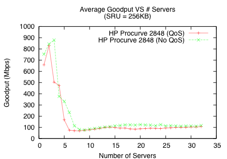
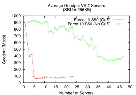
To ensure that the throughput collapse shown in Figure 2 is not an isolated instance, we study Incast on the three storage clusters described in §3.2. Figure 3 indicates that both the Procurve and S50 environments experience up to an order of magnitude drop in goodput (throughput as observed by the application). The E1200, however, did not exhibit any throughput drop for up to the 87 available servers, which we attribute to the large amount of buffer space available on the switch.
In our analysis, we use estimates of the output buffer sizes gathered from network administrators and switch specifications. Unfortunately, we are unable to determine the exact per-port buffer sizes on these switches.4 This information is not available because most switches dynamically allocate each link's output buffer from a shared memory pool. Also, when QoS queues are enabled, the amount of memory allocated to the queues depends on vendor-specific implementations. However, our estimates for output buffer sizes are corroborated by simulation results.
Many switches provide QoS support to enable prioritization of different kinds of traffic. A common implementation technique for providing QoS is to partition the output queue for each class of service. As a result, disabling QoS increases the effective size of the output queues, though the amount of this increase varies across different vendors and switches. As shown in Figure 3(a), disabling QoS on the Procurve environment does not significantly affect throughput – a collapse still occurs around 7 servers. In contrast, Figure 3(b) shows that disabling QoS on the Force10 S50 significantly delays the onset of Incast. These results suggest that the Force10 S50 allocates a relatively larger amount of buffer space and switch resources to QoS support in comparison to the Procurve 2848. Switch buffer sizes play an important role in mitigating Incast, as we evaluate in §4.3.
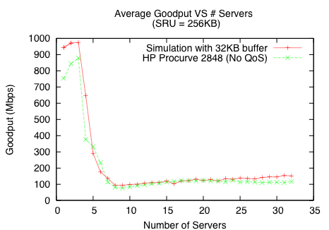
To determine how general a problem Incast is for cluster-based storage over TCP/IP/Ethernet, we also reproduce Incast in the ns-2 network simulator. Figure 4 shows Incast in simulation with an order of magnitude collapse at around 8 servers and beyond. These results closely match those from the Procurve environment. The differences between the results, including the difference in behavior below 3 servers, have a few possible causes. First, simulated source nodes serve data as rapidly as the network can handle, while real systems often have other slight delays. We attribute the lower performance of the real system between 1-3 servers to these differences. Also, simulation does not model Ethernet switching behavior, which may introduce small timing and performance differences.
Despite these differences, real world experiments validate our simulation measurements, showing that the impact of Incast is nearly identical in both real world system measurements and simulation.
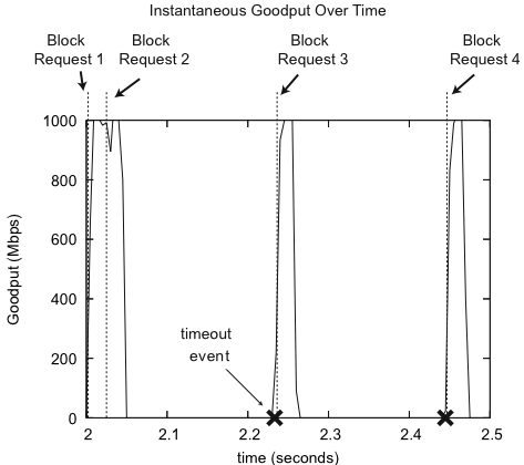
An analysis of the TCP traces obtained from simulation reveals that TCP retransmission timeouts are the primary cause of Incast (Figure 5).5 When goodput degrades, most servers still send their SRU quickly, but one or more other servers experience a timeout due to packet losses. The servers that finish their transfer do not receive the next request from the client until the client receives the complete data block, resulting in an underutilized link.
The rest of the paper assumes a familiarity with TCP terms and concepts. For a brief refresher on TCP, we refer the reader to the Appendix.
Reading blocks of data results in simultaneous transmission of packets from servers. Because the buffer space associated with the output port of the switch is limited, these simultaneous transmissions can overload the buffer resulting in losses. TCP recovers from losses by retransmitting packets that it has detected as being lost. This loss detection is either data-driven or is based on a timeout for a packet at the sender.
A TCP sender assigns sequence numbers to transmitted packets and expects TCP acknowledgements (ACKs) for individual packets from the receiver. The TCP receiver acknowledges the last packet it received in-order. Out-of-order packets generate duplicate ACKs for the last packet received in-order. Receiving multiple duplicate ACKs for a packet is an indication of a loss – this is data-driven loss detection. Timeouts are used as a fallback option in the absence of enough feedback, and are typically an indication of severe congestion.
In Figure 3(a), we see an initial drop from 900Mbps to 500Mbps between 3-5 servers on the Procurve. Analysis of TCP logs reveal that this drop in throughput is caused by the delayed ACK mechanism [3]. In the delayed ACK specification, an acknowledgement should be generated for at least every second packet and must be generated within 200ms of the arrival of the first unacknowledged packet. Most TCP implementations wait only 40ms before generating this ACK. This 40ms delay causes a “mini-timeout”, leading to underutilized link capacity similar to a normal timeout. However, normal timeouts are responsible for the order of magnitude collapse seen beyond 5 servers in Incast. We explore TCP-level solutions to avoid timeouts and to reduce the penalty of timeouts in detail in §5.
Finding Location Incast is caused by too-small switch output buffers: increasing buffer size can alleviate the situation. §4.3 TCP NewReno and SACK improve goodput considerably over TCP Reno, but do not prevent Incast.
§5.1.1 Improvements to TCP loss recovery using Limited Transmit or reducing the Duplicate ACK threshold do not help.
§5.1.2 Reducing the penalty of a timeout by lowering the minimum retransmission value can help significantly, but poses questions of safety and generality.
§5.2 Enabling Ethernet Flow Control is effective only in the very simplest setting, but not for more common multi-switched systems.
§6
Since timeouts are the primary cause of Incast, we try to prevent the root cause of timeouts – packet losses – to mitigate Incast by increasing the available buffer space allocated at the Ethernet switch. §4.1 mentioned that a larger switch buffer size delays the onset of Incast. Figure 6 shows that doubling the size of the switch's output port buffer in simulation doubles the number of servers that can transmit before the system experiences Incast.
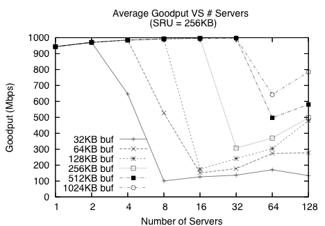
Figure 6: Effect of varying switch buffer size – doubling the size of the switch's output port buffer doubles the number of servers that can be supported before the system experiences Incast.
With a large enough buffer space, Incast can be avoided for a certain number of servers, as shown in Figure 6. This is corroborated by the fact that we were unable to observe Incast with 87 servers on the Force10 E1200 switch, which has very large buffers. But Figure 6 shows that for a 1024KB buffer, 64 servers only utilize about 65% of the client's link bandwidth, and doubling the number of servers only improves goodput to 800Mbps.
Unfortunately, switches with larger buffers tend to cost more (the E1200 switch costs over $500,000 USD), forcing system designers to choose between over-provisioning, future scalability, and hardware budgets. Furthermore, switch manufacturers may need to move to faster and more expensive memory (e.g., SRAM) as they move to 10Gbps and beyond. This move places cost pressure on manufacturers to keep buffer sizes small. Hence a more cost-effective solution other than increasing buffer sizes is required.
While the above experiments are run in a controlled environment with only one client reading from many servers, real storage environments are likely more complicated, with many clients making multiple concurrent requests to different sets of servers. Since the amount of buffer space available per client request likely decreases in common shared memory switch architectures (and does not increase otherwise), we expect overall performance to be worse in these more complex environments.
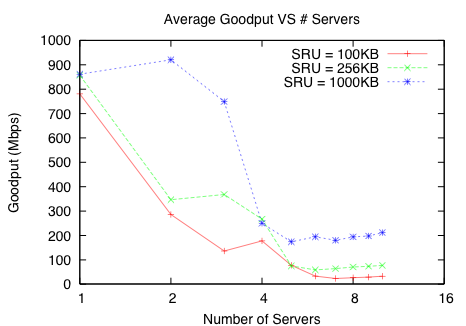
Figure 7 illustrates that increasing the SRU size improves the overall goodput. With 64 servers, the 1000KB SRU size run is two orders of magnitude faster than the 10KB SRU size run. Figure 8 shows that real switches, in this case the Force10 S50, behave similarly.
TCP performs well in settings without synchronized reads, which can be modeled by an infinite SRU size. The simple TCP throughput tests in netperf do not exhibit Incast [24]. With larger SRU sizes, servers will use the spare link capacity made available by any stalled flow waiting for a timeout event; this effectively reduces the ratio of timeout time to transfer time.
A large SRU size helps maximize disk head utilization on reads. Unfortunately, an SRU size of even 8MB is quite impractical: most applications ask for data in small chunks, corresponding to an SRU size range of 1-256KB. For example, when requesting an 8MB block from the storage system, one would like to stripe this block across as many servers as needed to saturate the link. In addition, a larger SRU size can increase lock contention due to overlapping writes, leading to poor write performance in file system implementations [9].
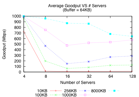
Figure 7: Effect of varying SRU size – for a given number of servers, a larger SRU improves goodput.
Figure 9 shows an alternative scaling model in simulation where the data block size is fixed and the number of storage servers are increased, placing an upper bound per request on the amount of pinned kernel memory in the client. This scaling model more closely resembles how file systems request data. A rapid drop-off in goodput is observed for a fixed block size as the number of servers increases. Because the data block size is fixed, increasing the number of servers reduces the SRU size. Thus, the effect of increasing the number of servers is compounded by a reduced SRU size and results in even lower goodput.
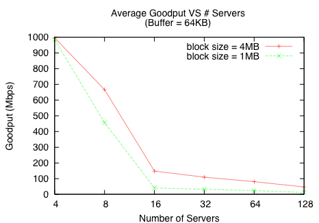
Figure 9: For a fixed data block size, as opposed to a fixed SRU size, increasing the number of servers also reduces the SRU size requested from each server and results in even lower goodput.
Because TCP timeouts are the primary reason that Incast hurts throughput, we analyze TCP-level solutions designed to reduce both the number and penalty of timeouts. We perform this analysis using ns-2 simulations.
In this section, we analyze three different approaches to avoiding timeouts by:
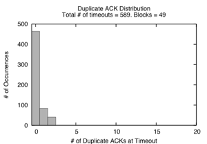
Analysis Method - Performance and Timeout Categorization: For each approach, we ask two questions: 1) how much does the approach improve goodput and 2) if timeouts still occur, why? To answer the second question, we look at the number of Duplicate ACKs Received at the point when a flow experiences a Timeout (the DART count). The purpose of this analysis is to categorize the situations under which timeouts occur to understand whether the timeout could have been avoided.
There are three types of timeouts that cannot be avoided by most TCP implementations. The first occurs when an entire window of data is lost and there is no feedback available for TCP to use in recovery, leading to a DART value of zero. We categorize this kind of timeout as a Full Window Loss.
The second type occurs when the last packet of an SRU is dropped and there is no further data available in this block request for data-driven recovery. We categorize this type of timeout as a Last Packet Loss case. We find, however, that there are relatively few Last Packet Loss cases.
The last unavoidable timeout situation occurs when a retransmitted packet triggered by TCP's loss recovery mechanism is also dropped. Since there is no way for the sender to know whether this retransmitted packet is dropped, the sender experiences a timeout before retransmitting the packet again. We categorize this unavoidable timeout as a Lost Retransmit. The DART count does not help in categorizing Lost Retransmit cases; we examine the TCP trace files to identify these situations.
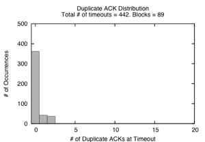
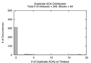
(a) Reno (b) NewReno (c) NewReno with dathresh=1.
Figure 11: Distribution of Duplicate Acknowledgements Received at a Timeout (DART) recorded for a 20s run with 16 servers, 64 packet switch buffer, 256KBytes SRU size.
Reno NewReno NewReno + dathresh=1 (Fig. 11(a)) (Fig. 11(b)) (Fig. 11(c)) data blocks transmitted 49 89 84 timeout events 589 442 349 full window losses 464 362 313 lost retransmits 61 2 41 lost retransmits when DART ≥ dathresh 0 0 34 lost retransmits when DART < dathresh 61 2 7 last packets dropped 2 5 2
Table 3: Categorization of timeout events under different TCP scenarios (corresponding to Figure 11)
Many TCP variants help reduce expensive timeouts by using acknowledgements to more precisely identify packet losses [19, 3, 13, 22]. A well-documented problem with the classic TCP Reno algorithm is that it recovers poorly from multiple losses in a window, leaving it susceptible to patterns of loss that cause a timeout [13]. For example, with a window size of six, Reno will always experience a timeout when the first two packets of the window are lost.
The most popular solutions to this problem are the improved retransmission algorithms in TCP NewReno [13] and the selective acknowledgements scheme in TCP SACK [22]. TCP NewReno, unlike Reno, does not exit fast recovery and fast retransmit when it receives a partial ACK (an indication of another loss in the original window), but instead immediately transmits the next packet indicated by the partial ACK. TCP SACK uses a selective acknowledgment scheme to indicate the specific packets in a window that need to be resent [12].
Figure 10 shows that both TCP NewReno and TCP SACK outperform TCP Reno. Note that TCP NewReno offers up to an order of magnitude better performance compared to TCP Reno in this example. Unfortunately, none of the TCP implementations can eliminate the large penalty to goodput caused by Incast.
Figure 11(a) and (b) shows the DART distribution for TCP Reno and NewReno, while Table 3 shows the categorization of timeout events. The total number of timeouts per data block is much lower for NewReno, partially explaining the goodput improvement over Reno. While most timeouts can be categorized as Full Window Loss cases or Lost Retransmit cases, there are still 78 timeouts that do not fall into these cases: they occur when the flows obtain some, but not enough feedback to trigger data-driven loss recovery. We next examine two schemes designed to improve these remaining cases.
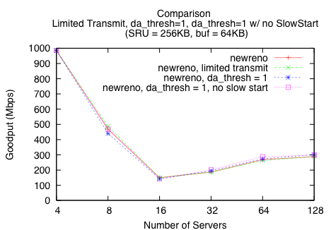
When a flow has a small window or when a sufficiently large number of packets in a large window are lost, Limited Transmit [2] attempts to ensure that enough packets are sent to trigger the 3 duplicate ACKs necessary for data-driven recovery. Alternatively, we can reduce the duplicate ACK threshold (dathresh) from 3 to 1 to automatically trigger fast retransmit and fast recovery upon receiving any duplicate acknowledgement.
Figure 12 illustrates that neither of these mechanisms provide any throughput benefit over TCP NewReno. We plot the DART distribution for setting dathresh=1 in Figure 11(c). The reduced retransmit variant successfully eliminates timeouts when only 1 or 2 duplicate ACKs were received. Unfortunately, this improvement does not increase goodput because each data block transfer still experiences at least one timeout. These remaining timeouts are mostly due to full window losses or lost retransmissions, which none of the TCP variants we study can eliminate.
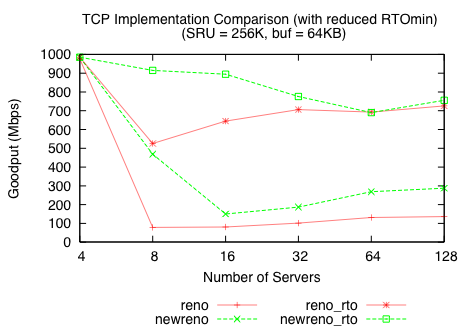
(a) Varying SRU sizes (b) Different TCP implementations
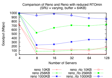
Figure 13: A lower RTO value (RTOmin = 200µs) in simulation improves goodput by an order of magnitude for both Reno and NewReno. rto represents runs with a modified RTOmin value.
Finally, we disable TCP slow-start to prevent network congestion produced by flows that exponentially increase their window sizes to discover link capacity following a timeout (or at the beginning of a TCP transfer). Figure 12 shows that forcing TCP flows to discover link capacity using only additive increase does not alleviate the situation. We leave an analysis of even more conservative congestion control algorithms for future work.
Because many of the TCP timeouts seem unavoidable (e.g. Full Window Loss, Lost Retransmit), here we examine reducing the time spent waiting for a timeout. While this approach can significantly improve goodput, this solution should be viewed with caution because it also increases the risk of premature timeouts, particularly in the wide-area [4]. We discuss the consequences of this effect below.
The penalty of a timeout, or the amount of time a flow waits before retransmitting a lost packet without the “fast retransmit” mechanism provided by three duplicate ACKs, is the retransmission timeout (RTO). Estimating the right RTO value is important for achieving a timely response to packet losses while avoiding premature timeouts. A premature timeout has two negative effects: 1) it leads to a spurious retransmission; and 2) with every timeout, TCP re-enters slow-start even though no packets were lost. Since there is no congestion, TCP thus would underestimate the link capacity and throughput would suffer. TCP has a conservative minimum RTO (RTOmin) value to guard against spurious retransmissions [29, 19].
Popular TCP implementations use an RTOmin value of 200ms [35]. Unfortunately, this value is orders of magnitude greater than the round-trip times in SAN settings, which are typically around 100µs for existing 1Gbps Ethernet SANs, and 10µs for Infiniband and 10Gbps Ethernet. This large RTOmin imposes a huge throughput penalty because the transfer time for each data block is significantly smaller than RTOmin.
Figure 13 shows that reducing RTOmin from 200ms to 200µs improves goodput by an order of magnitude for between 8 to 32 servers. In general, for any given SRU size, reducing RTOmin to 200µs results in an order of magnitude improvement in goodput using TCP Reno (Figure 13(a)). Figure 13(b) shows that even with an aggressive RTOmin value of 200µs, TCP NewReno still observes a 30% decrease in goodput for 64 servers.
Unfortunately, setting RTOmin to such a small value poses significant implementation challenges and raises questions of safety and generality.
Implementation Problems: Reducing RTOmin to 200µs requires a TCP clock granularity of 100µs, according the standard RTO estimation algorithm [29, 19]. BSD TCP and Linux TCP implementations are currently unable to provide this fine-grained timer. BSD implementations expect the OS to provide two coarse-grained “heartbeat” software interrupts every 200ms and 500ms, which are used to handle internal per-connection timers [5]; Linux TCP uses a TCP clock granularity of 1 to 10ms. A TCP timer in microseconds needs either hardware support that does not exist or efficient software timers [6] that are not available on most operating systems.
Safety and Generality: Even if sufficiently fine-grained TCP timers were supported, reducing the RTOmin value might be harmful, especially in situations where the servers communicate with clients in the wide-area. Allman et. al. [4] note that RTOmin can be used for trading “timely response with premature timeouts” but there is no optimal balance between the two in current TCP implementations: a very low RTOmin value increases premature timeouts. Earlier studies of RTO estimation in similar high-bandwidth, low-latency ATM networks also show that very low RTOmin values result in spurious retransmissions [34] because variation in the round-trip-times in the wide-area clash with the standard RTO estimator's short RTT memory.
Some Ethernet switches provide a per-hop mechanism for flow control that operates independently of TCP's flow control algorithm. When a switch that supports Ethernet Flow Control (EFC) is overloaded with data, it may send a “pause” frame to the interface sending data to the congested buffer, informing all devices connected to that interface to stop sending or forwarding data for a designated period of time. During this period, the overloaded switch can reduce the pressure on its queues.
We find that EFC is effective in the simplest configuration (i.e. all clients and servers connected to one switch), but does not work well with more than one switch, has adverse effects on other flows in all configurations, and is inconsistently implemented across different switches.
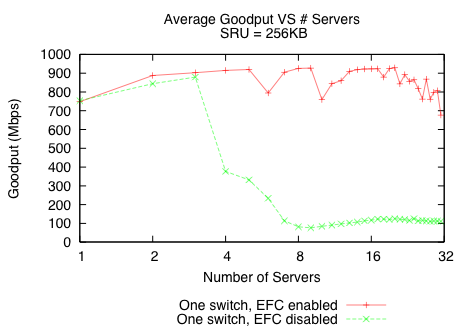
We measure the effect of enabling Ethernet Flow Control on a single HP Procurve 2848 switch, where one client and multiple servers are directly connected to the switch. Figure 14 shows that EFC can significantly improve performance. Unfortunately, TCP goodput is still highly variable and is lower than it would be without Incast.
Despite its potential benefits, our simple network topology and workload hide adverse side effects that surface when EFC is used on larger multi-switch networks with many more clients and active TCP flows. For many of these reasons, most switch vendors and network operators keep EFC inactive.
The most significant problem with EFC is head-of-line blocking, which occurs when a pause frame originating from one congested interface stops several other flows from communicating simultaneously. The effects of head-of-line blocking can be particularly severe in heterogeneous bandwidth settings where one slow link can cause other faster links to be underutilized. In other words, pause frames pause all traffic entering an interface, regardless of whether that traffic is causing congestion.
Due to the complexities of head-of-line blocking, and because the particular interactions of EFC across multiple switches is inconsistently implemented across switch vendors, enabling EFC effectively across more than one switch can be a difficult or impossible task. For instance, in order to provide link aggregation between two HP Procurve 2848 switches, our system was configured with a virtual interface for the trunk – a configuration over which the switch did not support flow control.
While Ethernet Flow Control currently interacts adversely with other flows, a number of recent Ethernet initiatives have been introduced to add congestion management with rate-limiting behavior and to improve the pause functionality with a more granular per-channel capability [39]. These initiatives are part of a larger movement to create a lossless and flow-controlled version of Ethernet, referred to as Data Center Ethernet, which will allow the consolidation of multiple communication fabrics (including storage networks running Fibre Channel) into a single Ethernet solution.
Truly lossless behavior at the Ethernet level is a valid solution to the Incast problem, but it will take a number of years before these new standards are implemented in switches, and even then there are no guarantees that new switches will implement these standards uniformly or that they will be as commoditized and inexpensive as current Ethernet switches.
Providing storage via a collection of storage servers networked using commodity TCP/IP/Ethernet components is an increasingly popular approach. The Incast problem studied comprehensively in this paper has been noted previously by several researchers (e.g., [15, 17, 25, 24]) while developing this cluster-based approach.
Nagle et al. briefly discussed the switch buffer overruns caused by clients reading striped data in a synchronized many-to-one traffic pattern [25]. Upgrading to better switches with larger buffer sizes was one adopted solution. They also mentioned the possibility of using link-level flow control, but highlight the difficulties of such an approach for different non-trivial switch topologies without incorporating higher-level striping information used by the storage system.
In later work, Nagle et al. again report on the effects of Incast on scalable cluster-based file storage performance [24]. Specifically, they report on experiments with a production-quality system where a single client reads a file sequentially using an 8MB synchronization block size striped across multiple storage servers. As the number of storage servers is increased for their system, keeping all other variables of the network constant, the authors observe a linear scaling of storage bandwidth for up to 7 storage servers, a steady plateau until around 14 servers, and then a rapid drop-off. The primary cause of this performance collapse was attributed to multiple senders overwhelming the buffer size of the network switch. This prior work also observed that the Incast problem does not appear when running a streaming network benchmark like netperf. Therefore, the performance collapse is also attributed to the synchronized and coordinated reads in a cluster-based storage environment. Nagle et al. also discuss modest performance gains when using SACK or reducing the length of TCP retransmission timeouts. Although this last point is not quantified, they observe that degraded performance still persists even with these changes.
At a higher level, the Incast problem is a particular form of network congestion, a topic which has been studied extensively in different environments. Early work on congestion control in the wide-area network by Van Jacobson addressed the TCP congestion collapse of the Internet around 1985 [19]. Adopted as the basis of TCP congestion control, the idea was to provide a method for a networked connection to discover and dynamically adjust to the available end-to-end bandwidth when transferring data. Chiu and Jain describe why the window mechanism of “additive increase / multiplicative decrease” achieves fairness and stability in this setting [10].
Unfortunately, TCP's congestion control and avoidance algorithms are not directly applicable to all settings. For example, they are known to have problems in wireless settings, where packet losses may not actually be caused by congestion. TCP also has problems in high-latency, high-bandwidth network settings [20]. The Incast problem provides another example of a network setting where using TCP may cause poor performance.
The performance and fairness of TCP when many flows share the same bottleneck was studied by Morris [23]. As the number of TCP flows through a bottleneck increases to the point where there are more flows than packets in the bandwidth-delay product, there is an increasingly high loss rate and variation of unfair bandwidth allocation across flows. This paper applies some of Morris's methods and analysis techniques to the synchronized reads setting that produces Incast.
Incast occurs when a client simultaneously receives a short burst of data from multiple sources, overloading the switch buffers associated with its network link such that all original packets from some sources are dropped. When this occurs, the client receives no data packets from those sources and so sends no acknowledgement packets, requiring the sources to timeout and then retransmit. Often, the result of these TCP timeouts is an order of magnitude decrease in goodput.
Unfortunately, this traffic pattern is very common for the growing class of cluster-based storage systems. When data is striped across multiple storage nodes, each client read creates this pattern and large sequential reads create it repeatedly (once for each full stripe).
Whether or not Incast will cause goodput collapse in a system depends on details of the TCP implementation, network switch (especially buffer sizes), and system configuration (e.g., the number of servers over which data is striped). Unfortunately, avoiding collapse often requires limiting striping to a small number of servers. Techniques such as very short timeouts and link-level flow control can mitigate the effects of Incast in some circumstances, but have their own drawbacks. No existing solution is entirely satisfactory, and additional research is needed to find new solutions by building on the understanding provided by this paper.
We are grateful to Jeff Butler, Abbie Matthews, and Brian Mueller at Panasas Inc. for helping us conduct experiments on their systems. We thank Michael Stroucken for his help managing the PDL cluster. We thank our paper shepherd Ric Wheeler, Michael Abd-El-Malek, and all of our reviewers for their feedback. We also thank the members and companies of the PDL Consortium (including APC, Cisco, EMC, Google, Hewlett-Packard, Hitachi, IBM, Intel, LSI, Microsoft, Network Appliance, Oracle, Seagate, and Symantec) for their interest, insights, feedback, and support.
This material is based on research sponsored in part by the National Science Foundation, via grants #CNS-0546551, #CNS-0326453 and #CCF-0621499, by the Army Research Office under agreement number DAAD19–02–1–0389, by the Department of Energy under award number DE-FC02-06ER25767, and by DARPA under grant #HR00110710025. Elie Krevat is supported in part by an NDSEG Fellowship from the Department of Defense.
We provide the reader with a brief background on TCP for the purposes of understanding the terms used in this paper. While we skip many of the detailed nuances of TCP, we refer the reader to several well known resources for further TCP details [33, 3, 11, 38, 30, 26].
The Transmission Control Protocol (TCP) [33] is a connection-oriented protocol that guarantees a reliable, in-order byte-stream communication service between two processes, in contrast to the best-effort connectionless datagram delivery service provided by the User Datagram Protocol (UDP) [31]. Both TCP and UDP use the Internet Protocol (IP) [32], a best-effort datagram service, to carry their messages. The use of TCP is attractive for applications that perform pairwise communication as it offers the following advantages:
A TCP connection is Full Duplex – once a TCP connection is established between two end-points using a 3-way handshake protocol, the connection supports a pair of byte streams, one in each direction. TCP transfers a byte-stream by bundling together contiguous bytes into a TCP segment or packet.
A TCP packet, encapsulated in an IP packet, may be dropped en-route to the destination due to several causes, such as 1) the sender's kernel buffer being full, 2) a router buffer on the path to the destination being full, 3) routing errors, or 4) the receiver's kernel buffer being full. TCP uses a positive acknowledgement scheme with retransmissions to achieve reliable data transfer. To assist in the in-order delivery of data at the receiver, the TCP sender assigns a sequence number to every byte of data sent over a TCP connection. For a given packet, the sequence number assigned to the packet is the sequence number of the first byte within the packet. TCP uses a cumulative acknowledgment scheme: the ACK packet contains a sequence number informing the sender that it has received all bytes up to, but not including, that sequence number. While TCP assigns sequence numbers based on bytes, for simplicity, we discuss sequence numbers based on packets.
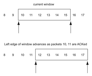
To make efficient use of the link, TCP uses a sliding window algorithm to keep multiple packets in flight. A window defines the number of packets that are unacknowledged: the left-edge of the window indicates the first packet not acknowledged by the receiver. For example, as shown in Figure 15, if the sender's window has a left-edge sequence number of 10 and a window size of 6, then the receiver has acknowledged the receipt of all packets with a sequence number less than 10, and the sender can transmit packets 10-15 all at once. When packets 10 and 11 reach the receiver, the receiver sends an ACK for packets 11 and 12 respectively. Since the left edge of the window now starts at 12 and the window size is 6, the sender may now transmit packets 16 and 17.
If a packet is delivered to a TCP receiver out-of-order, either due to re-ordering or losses in the network, the receiver generates a duplicate ACK for the last packet it received in-order. Building on the example above, if packet 12 was dropped by the network, then on receiving packet 13, the TCP receiver generates an ACK for packet 12 instead of packet 14, and the left edge of the window is not advanced.
A TCP sender detects a packet loss using the two schemes described below. Once a packet loss is detected, a TCP sender recovers from the loss by retransmitting the packet.
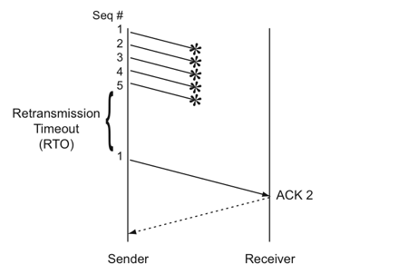
Timeout driven loss recovery: Consider the case shown in Figure 16(a). Packets 1 to 5 sent by the sender are all dropped. The sender waits for a certain amount of time, defined by the retransmission timeout (RTO), before a timeout event indicates the possible loss of packet 1, at which point the sender recovers from the loss by retransmitting packet 1. The RTO value is based on the round trip time (RTT), which is an estimated value.
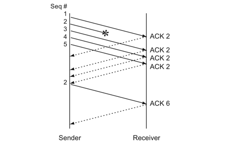
Data driven loss recovery: A duplicate ACK can be used as an indication of loss, but it could also be generated due to packet reordering in the network. To distinguish benign reordering from actual loss, TCP senders normally consider 3 duplicate ACKs for a packet as an indication of a loss. Figure 16(b) shows a case where a sender transmits 5 packets but the second packet is lost. Packets 3, 4, and 5 generate duplicate ACKs indicating that packet 2 is lost. On getting 3 duplicate ACKs for packet 2, the sender assumes that packet 2 is lost and retransmits it: this is called fast retransmit. On receiving packet 2, the receiver ACKs packet 6, the next in-order packet it expects from the sender. Data-driven loss recovery responds to losses more quickly than timeout-driven recovery.
TCP provides end-to-end flow control whereby the receiver can control the amount of data a sender transmits. With every ACK, the receiver returns a window size indicating the number of packets a sender may transmit.
(a) Timeout-driven Recovery (b) Data-driven Recovery.
TCP is adaptive – flows utilize available bandwidth by probing the network. On startup and following a timeout, TCP has no good estimate of the capacity of the end-to-end path, so it enters slow-start to discover the capacity. For every ACKed packet received, the sender grows its window by 1. This results in an exponential growth in the window size and, hence, in the sending rate.
Congestion occurs when the sending rate exceeds the available bandwidth and packets are dropped. Various TCP algorithms have been designed to deal with congestion – they do this by reacting to congestion (indicated by loss) by throttling the rate at which the sender transmits data. Under data-driven loss recovery, the sender performs a multiplicative decrease by halving its window (also accompanied by fast-recovery) and begins an additive increase (or congestion avoidance) phase, where for every window of data acknowledged by the receiver, the sender increases its window size by 1. Under timeout-driven recovery, the sender reduces its window to 1, performs slow-start until a certain threshold, and then enters the congestion avoidance phase.
This document was translated from LATEX by HEVEA.