|
||||||||||||||
|
Xiapu Luo and Rocky K. C. Chang
Department of Computing
The Hong Kong Polytechnic University
Hung Hom, Kowloon, Hong Kong, SAR, China
Email: {csxluo|csrchang}@comp.polyu.edu.hk
Therefore, it is important to measure packet reordering [17] and to quantify the degree of reordering [13,14]. Previous works have studied various characteristics of packet reordering, such as its frequency, magnitude, and its relationship with other factors. They can be categorized into two main classes--passive measurement [15] and active measurement [1,2,3,5,6,16,17,18]. In this paper, we concentrate on the active measurement approaches, which can be further classified into two groups. The first is referred to as bulk-transport based measurement that exchanges a relatively large amount of real application traffic between many participating sites [1,3,5,6,16]. The second is packet-train based measurement that sends a train of probing packets, and the feedback information is then used to infer the presence of packet reordering [2,17,18].
The main advantage of the bulk-transport based measurement is their ability to measure the impact of packet reordering on real applications and on different transport protocols. Moreover, they can observe the packet reordering phenomena in both the forward-path and backward-path by examining traffic traces in different directions. However, these approaches require coordinations among various participating sites, which obviously cannot be done easily for an arbitrarily large network scale. The packet-train based measurement, on the other hand, allows any Internet host to measure packet reordering on the paths between itself and any other host. Moreover, this approach usually requires only a small number of packets to conduct the measurement.
The focus of this paper is on the packet-train based measurement methods, which unfortunately still suffer from a number of practical limitations. First, the ICMP and TCP packets used in the ICMP-based approach [2] and the TCP SYN Test [17] are often rate-limited or even filtered by firewalls [19]. Second, both the Dual Connection Test [17] and Tulip [18] rely on the assumption that the ID field in the IP header (IPID) increases monotonically across TCP connections for the same server. This assumption, unfortunately, does not hold in some popular systems, such as Linux and OpenBSD. Third, the Single Connection Test [17] may yield inaccurate results due to the delayed acknowledgment algorithm. The Dual Connection Test also suffers from inaccurate results in the presence of load balancing schemes. Fourth, both the TCP Data Transfer Test [17] and the ICMP-based method [2] cannot distinguish all packet reordering scenarios. Moreover, all the aforementioned methods detect end-to-end packet reordering. That is, two packets can arrive inorder even though they may be reordered in an even number of times on the path.
In this paper we propose three new methods to end-to-end packet reordering measurement, which can detect all four reordering cases: no-reordering, forward-path reordering, backward-path reordering, and dual-path reordering. Since they use TCP data as probing messages in a single connection, the probing messages and the responses will not be filtered by firewalls or routers. Moreover, each measurement is conducted in one TCP session; therefore, the measurement result will not be affected by a content-blind load balancing scheme. To reduce the impact on the normal network traffic, each method injects only a minimal number of packets into the network, and the size of the response packets is also small.
The three methods differ from each other only in the mechanisms to
trigger the required responses from the remote host, catering for
the diverse TCP implementations in the Internet. Another important
feature of our methods is that they only rely on the TCP sliding
window protocol, which is supported by all TCP variants (e.g. TCP
Tahoe, TCP Reno, TCP NewReno, etc.) [21,22]. Moreover, our
approaches make use of customized receiving window size and MSS
(Maximum Segment Size) to control the number and size of response
packets. Furthermore, we have employed a timeout mechanism to
discard suspicious samples as a result of packet losses. We have
implemented the three methods in a tool called POINTER, and have
thoroughly tested and verified the approaches in a test-bed and
![]() websites.
websites.
The rest of the paper is organized as follows. In section 2, we introduce the principles behind the three new approaches, including a short review on the TCP sliding window protocol. Based on the general approach, we detail in section 3 the three measurement methods. In section 4, we present the measurement results obtained from a test-bed and the Internet for the validation of the methods. Moreover, we have analyzed the correlation of packet reordering events on a backward path from two websites, and discovered that they share the same path where packet ordering occurs. We finally conclude this paper in section 5 with current work.
The result of Corollary 1 gives us a hint in
designing a comprehensive and effective reordering detection
scheme. First of all, consider that the server responds with ![]() and
and ![]() upon receiving
upon receiving ![]() and
and ![]() in order. That is, if there
is no forward-path reordering,
in order. That is, if there
is no forward-path reordering, ![]() will be generated first and
then followed by
will be generated first and
then followed by ![]() . Therefore, the order of receiving
. Therefore, the order of receiving ![]() and
and
![]() on the client side can differentiate between the cases of
no-ordering and backward-ordering.
on the client side can differentiate between the cases of
no-ordering and backward-ordering.
To trigger the third response ![]() , we need an ``erroneous event'' taken place at the server. The novelty here
is that we use the reordering of
, we need an ``erroneous event'' taken place at the server. The novelty here
is that we use the reordering of ![]() and
and ![]() to serve as the erroneous event. That is, if there is
forward-path reordering, the receiver will be compelled to send
to serve as the erroneous event. That is, if there is
forward-path reordering, the receiver will be compelled to send ![]() and another normal response (
and another normal response (![]() or
or ![]() ).
For instance, the receiver responds with
).
For instance, the receiver responds with ![]() first and then
first and then ![]() . Then the order of receiving them by the
client can differentiate between the cases of forwarding-reordering and dual-path reordering.
. Then the order of receiving them by the
client can differentiate between the cases of forwarding-reordering and dual-path reordering.
Based on the discussion above, we only need a pair of probing messages ![]() and
and ![]() to detect all four
reordering cases. Note that we have so far assumed no packet losses and a reasonable amount of latency between
the message arrivals at the server. Moreover, the server's responses to
to detect all four
reordering cases. Note that we have so far assumed no packet losses and a reasonable amount of latency between
the message arrivals at the server. Moreover, the server's responses to ![]() and
and ![]() only depend on the
information inscribed in the messages and the relative order of the two messages received by the server. We will
address the effect of packet losses and the solution to them in section 3.4. In the next section, we first
present several possibilities of selecting
only depend on the
information inscribed in the messages and the relative order of the two messages received by the server. We will
address the effect of packet losses and the solution to them in section 3.4. In the next section, we first
present several possibilities of selecting ![]() and
and ![]() based on the TCP sliding window mechanism.
based on the TCP sliding window mechanism.
| Name | Description | |
| SND.UNA | Oldest unacknowledged sequence number (SN) | |
| SND.NXT | SN of the next segment to be sent | |
| SND.WND | Size of the send window | |
| RCV.NXT | SN of the next segment to be received | |
| RCV.WND | Size of the receive window | |
| SEG.ACK | Acknowledgment number (AN) of a segment | |
| SEG.SEQ | First SN of a segment | |
| SEG.LEN | The length of a segment in bytes |
In our proposed methods, a client sends a probing message pair to induce two TCP data segments from the server when there is no packet reordering on the forward path, i.e., the probing message pair passes all eight steps. On the other hand, the reordering of the probing message pair, which is perceived as an erroneous event at the server, will induce the transmission of a pure ACK and a data segment. There are altogether three ways of generating the pure ACK.
First of all, a pure ACK can be generated as a result of not passing step 1 where a TCP receiver performs a sequence number check (SNC). The purpose of the SNC is to determines whether the received segment's SN is acceptable according to Eq. (1) or Eq. (2). If the segment fails the SNC (an erroneous event), some TCP implementations will drop the segment and return a pure ACK whose value is specified in the second part of Eq. (3).
A pure ACK can also be generated as a result of not passing step 5, where
a TCP receiver performs an acknowledgment number check (ANC) based on
Eq. (4).
If the ACK is acceptable, the receiver will update its send window by setting
SND.UNA = SEG.ACK. Otherwise, if SEG.ACK ![]() SND.UNA, i.e., a duplicate ACK, the receiver will ignore
it. Moreover, if SEG.ACK
SND.UNA, i.e., a duplicate ACK, the receiver will ignore
it. Moreover, if SEG.ACK ![]() SND.NXT (an erroneous event), i.e., acknowledging bytes
that have not been sent, some TCP implementations will drop the segment and
send back a pure ACK whose value is specified in the second part of Eq. (3).
SND.NXT (an erroneous event), i.e., acknowledging bytes
that have not been sent, some TCP implementations will drop the segment and
send back a pure ACK whose value is specified in the second part of Eq. (3).
Finally, if a TCP implementation does not respond to both failed SNC and failed ANC, a pure ACK can still be
induced by sending a out-of-ordered segment. Accordingly, we have designed three different probing message pairs
based on the server's responses discussed above. The corresponding methods are referred to as ![]() (ACknowledgment based Measurement) for the response to a failed SNC,
(ACknowledgment based Measurement) for the response to a failed SNC, ![]() (Sequence number and
ACK based Measurement) for the response to a failed ANC, and
(Sequence number and
ACK based Measurement) for the response to a failed ANC, and ![]() for the response to a out-of-order segment.
for the response to a out-of-order segment.
We have tested ![]() common systems to observe their responses to the failed SNC and
failed ANC. As shown in Table 2, the majority
of the tested systems responded to unacceptable ACKs. Therefore, the ACM method
can be applied to detect packet reordering on the paths to these systems. Although
the Linux systems do not respond to unacceptable ACKs, they respond to unacceptable
SNs. Thus, the SAM1 method can be applied to them. Finally, the SAM2 method
can be applied to the VM and HP-UX systems which ignore both unacceptable ACKs
and unacceptable SNs.
common systems to observe their responses to the failed SNC and
failed ANC. As shown in Table 2, the majority
of the tested systems responded to unacceptable ACKs. Therefore, the ACM method
can be applied to detect packet reordering on the paths to these systems. Although
the Linux systems do not respond to unacceptable ACKs, they respond to unacceptable
SNs. Thus, the SAM1 method can be applied to them. Finally, the SAM2 method
can be applied to the VM and HP-UX systems which ignore both unacceptable ACKs
and unacceptable SNs.
| Operating systems | Response to | Response to | Measurement | |
| unacceptable SNs | unacceptable ACKs | Methods | ||
| NT4/Win98, Win2000, WinXP, Win2003, | ||||
| MaxOSX, NetWare, SCO UNIX, NetBSD, | Not tested | Send a pure ACK | ACM | |
| AIX, OS/2, IRIX, Tru64, FreeBSD, | ||||
| Solaris 9 , Solaris 8, Solaris*, OpenVMS | ||||
| Linux | Send a pure ACK | No response | SAM1 | |
| VM and HP-UX | No response | No response | SAM2 |
The probing session can be carried out at any time in the ESTABLISHED state.
To keep the following discussion simple, however, we start the probing procedure
immediately after the TCP three-way handshake is completed. The notations used
in the remaining of this paper are summarized in Table
3, and the segments involved in the 3-way handshaking are given in Table
4. Note that these segment exchanges are the same for all three methods.
![]() and
and ![]() are the initial SNs for the client and server, respectively. In
are the initial SNs for the client and server, respectively. In
![]() , the client initiates a SYN segment with a small advertised
window size of
, the client initiates a SYN segment with a small advertised
window size of ![]() . The main function of the small window size is to ensure that the
server will adopt
. The main function of the small window size is to ensure that the
server will adopt ![]() for its send window size. Therefore, even before issuing the HTTP
request in
for its send window size. Therefore, even before issuing the HTTP
request in ![]() , the client is able to predict correctly that the server will return
one data segment and the size of the TCP payload (
, the client is able to predict correctly that the server will return
one data segment and the size of the TCP payload (![]() ), provided that the size of the requested document is larger than
), provided that the size of the requested document is larger than
![]() . The packet sequence concerned is shown in (3)-(5) in Table 4.
As we shall see later, the ANs in the probing message pair are the same for
all three methods, because they all exploit the predicability of the server's
payload through the small
. The packet sequence concerned is shown in (3)-(5) in Table 4.
As we shall see later, the ANs in the probing message pair are the same for
all three methods, because they all exploit the predicability of the server's
payload through the small ![]() . However, they differ in their SNs and the TCP payloads.
. However, they differ in their SNs and the TCP payloads.
| Notations | Description | |
|
|
The |
|
|
|
The |
|
|
|
The TCP SYN packet sent by the client | |
|
|
The TCP SYN/ACK packet responded by the server | |
|
|
|
|
|
|
Size of |
|
|
|
|
|
|
|
|
|
|
|
|
|
|
|
The size of the client's advertised window | |
|
|
The size of the server's advertised window |
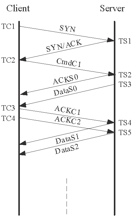
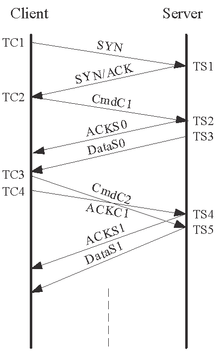
If these two ACKs arrive at the server in order (Figs. 1(a)
and 1(c)), the server will expectedly transmit two data
segments ![]() and
and ![]() , one after the other, which contain the requested document. The
order that
, one after the other, which contain the requested document. The
order that ![]() and
and ![]() are received at the client can then be used to differentiate between
the no-ordering and backward-path ordering cases.
are received at the client can then be used to differentiate between
the no-ordering and backward-path ordering cases.
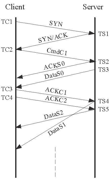
However, if these two ACKs are reordered in the forward path (Figs. 1(b)
and 1(d)), the server will discover that ![]() is an unacceptable ACK, because
is an unacceptable ACK, because
![]() and
and
![]() at the time of receiving the ACK. In this
case, the server, which is implemented under the first group of systems in
Table 2, is expected to drop
at the time of receiving the ACK. In this
case, the server, which is implemented under the first group of systems in
Table 2, is expected to drop ![]() and to send back a pure ACK
and to send back a pure ACK ![]() . When
. When ![]() , the first ACK, later arrives, the server will send out the requested
data in
, the first ACK, later arrives, the server will send out the requested
data in ![]() . Thus, the order of receiving
. Thus, the order of receiving ![]() and
and ![]() can be used to differentiate between the forward-path and dual-path
reordering cases.
can be used to differentiate between the forward-path and dual-path
reordering cases.
|
 |
 |
 |
|
(a) No reordering |
(b) Forward-path reordering | (c) backward-path reordering | (d) Dual-path reordering |
| No. | Segment | Sequence | Acknowledgment | Segment Type | Payload |
| Number | Number | Length | |||
| The probing message pair | |||||
| 6 | |
|
|
Pure ACK ( |
0 |
| 7 | |
|
|
Pure ACK ( |
0 |
| Server's responses in the absence of packet reordering in the forward path | |||||
| 8 | |
|
|
HTTP reply ( |
|
| 9 | |
|
|
HTTP reply ( |
|
| Server's responses in the presence of packet reordering in the forward path | |||||
| 8' | |
|
|
Pure ACK ( |
0 |
| 9' | |
|
|
HTTP reply ( |
|
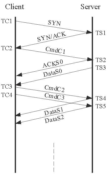
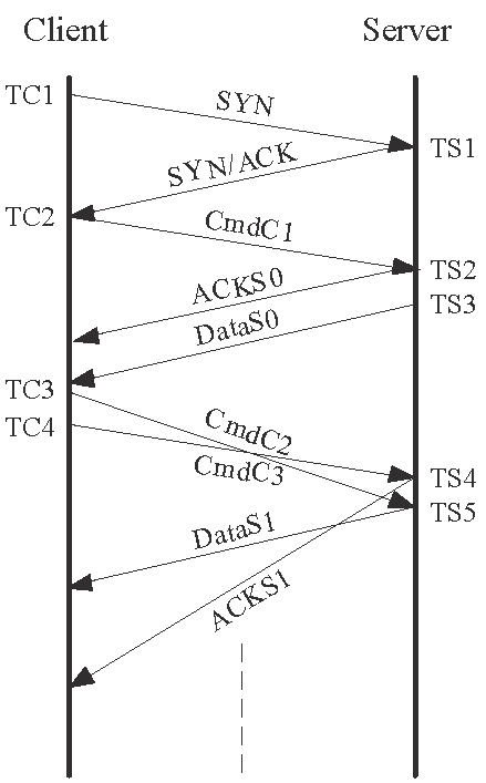
From the parameters in Table 6, it is not difficult
to see that the server will send two more data segments, each in the size of
![]() , in response to the probing message pair when there is no forward-path
reordering. Therefore, the order of receiving the two data segments can be used
to differentiate between the no-ordering and backward-path reordering cases.
, in response to the probing message pair when there is no forward-path
reordering. Therefore, the order of receiving the two data segments can be used
to differentiate between the no-ordering and backward-path reordering cases.
On the other hand, if the probing message pair is reordered (Figs. 2(b)
and 2(d)), ![]() will fail the SNC on the server side, because the SN falls outside
the legal range according to Eq. (2). Specifically,
from Table 6,
will fail the SNC on the server side, because the SN falls outside
the legal range according to Eq. (2). Specifically,
from Table 6, ![]() 's SN is given by
's SN is given by
![]() (
(![]() ) and
) and
![]() (0 payload length). On the other hand, at the time
of receiving
(0 payload length). On the other hand, at the time
of receiving ![]() , the server's states as a TCP receiver are given by
, the server's states as a TCP receiver are given by
![]() and
and
![]() . According to Eq. (2),
. According to Eq. (2),
![]() 's SN is therefore illegal, i.e.,
's SN is therefore illegal, i.e.,
![]() . As discussed
before, the server is therefore expected to discard this pure ACK and to respond
with an ACK (
. As discussed
before, the server is therefore expected to discard this pure ACK and to respond
with an ACK (![]() ). When
). When ![]() that contains a correct SN arrives, the server will clearly respond
with
that contains a correct SN arrives, the server will clearly respond
with ![]() . Therefore, the order of receiving
. Therefore, the order of receiving ![]() and
and ![]() can differentiate between the backward-path reordering and dual-path
reordering cases. Thus, unlike the
can differentiate between the backward-path reordering and dual-path
reordering cases. Thus, unlike the ![]() method that sends out two pure ACKs, this method sends a second
HTTP request, so that the TC4's SN is different from TC3's.
method that sends out two pure ACKs, this method sends a second
HTTP request, so that the TC4's SN is different from TC3's.

|
 |
 |
 |
| (a) No reordering |
(b) Forward-path reordering | (c) backward-path reordering | (d) Dual-path reordering |
| No. | Segment | Sequence | Acknowledgment | Segment Type | Payload |
| Number | Number | Length | |||
| The probing message pair | |||||
| 6 | |
|
|
HTTP request ( |
|
| 7 | |
|
|
Pure ACK ( |
0 |
| Server's responses in the absence of packet reordering in the forward path | |||||
| 8 | |
|
|
HTTP reply ( |
|
| 9 | |
|
|
HTTP reply ( |
|
| Server's responses in the presence of packet reordering in the forward path | |||||
| 8' | |
|
|
Pure ACK ( |
0 |
| 9' | |
|
|
HTTP reply ( |
|
Same as the ACM method, the total size of the requested document
must be at least
![]() to ensure a proper working of this
method. In terms of the overhead, the size of the probing message
pair for the
to ensure a proper working of this
method. In terms of the overhead, the size of the probing message
pair for the ![]() method is larger than that in the
method is larger than that in the ![]() method
by
method
by ![]() bytes, the size of the second HTTP request message.
However, the maximum amount of HTTP data returned by the server is
the same for both methods, i.e.,
bytes, the size of the second HTTP request message.
However, the maximum amount of HTTP data returned by the server is
the same for both methods, i.e.,
![]() bytes.
bytes.
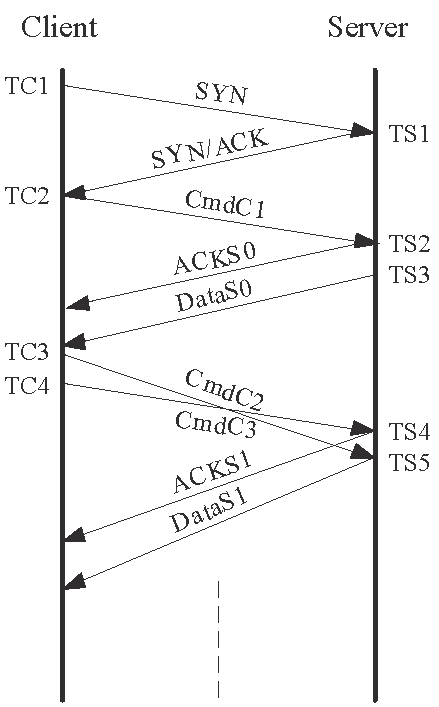
Similar to the ![]() method, the probing message pair uses different SNs. However,
notice from Table 7 that the SNs are offset by
method, the probing message pair uses different SNs. However,
notice from Table 7 that the SNs are offset by ![]() and
and
![]() respectively, where
respectively, where ![]() is a small value. That is, both messages contain unexpected but
acceptable SN (out-of-order segments). Therefore, the recipient of
is a small value. That is, both messages contain unexpected but
acceptable SN (out-of-order segments). Therefore, the recipient of ![]() will enable the server to advance its send window and to send a
data segment. When
will enable the server to advance its send window and to send a
data segment. When ![]() later reaches the server, this segment acknowledges all the outstanding
data sent by the server (AN =
later reaches the server, this segment acknowledges all the outstanding
data sent by the server (AN =
![]() ); therefore, the server will also advance
its send window. As a result, the server will reply with another data segment
); therefore, the server will also advance
its send window. As a result, the server will reply with another data segment
![]() . The server therefore responds with a total of two data segments
whose order of arriving at the client can be used to differentiate between the
no-ordering and backward-path reordering cases.
. The server therefore responds with a total of two data segments
whose order of arriving at the client can be used to differentiate between the
no-ordering and backward-path reordering cases.
If the two messages are reordered, as shown in Figs. 3(b)
and 3(d), the message ![]() contains an unacceptable ACK. However, the HP-UX and VM
server will ignore the illegal AN, but, similar to other TCP implementations,
it will definitely respond to the out-of-ordered segment with a duplicate ACK,
contains an unacceptable ACK. However, the HP-UX and VM
server will ignore the illegal AN, but, similar to other TCP implementations,
it will definitely respond to the out-of-ordered segment with a duplicate ACK,
![]() . There is a minor difference between the HP-UX and VM systems though.
. There is a minor difference between the HP-UX and VM systems though.
![]() contains a SN of
contains a SN of ![]() for an HP-UX server) whereas
for an HP-UX server) whereas ![]() contains a SN of
contains a SN of ![]() for a VM server, and both contain an AN of
for a VM server, and both contain an AN of ![]() . However, this difference does not affect our measurement method,
and in fact it can be used to remotely identify these two systems [19]. On the other hand, the second message
. However, this difference does not affect our measurement method,
and in fact it can be used to remotely identify these two systems [19]. On the other hand, the second message ![]() contains an acceptable AN of
contains an acceptable AN of ![]() . In this case, the server will advance its
. In this case, the server will advance its
![]() and reply with a data segment
and reply with a data segment ![]() with
with
![]() and
and ![]() . Therefore, the order of receiving the ACK and data segment
from the server can be used to differentiate between the backward-path reordering
and dual-path reordering cases.
. Therefore, the order of receiving the ACK and data segment
from the server can be used to differentiate between the backward-path reordering
and dual-path reordering cases.
|
 |
 |
 |
| (a) No reordering |
(b) Forward-path reordering | (c) backward-path reordering | (d) Dual-path reordering |
| No. | Segment | Sequence | Acknowledgment | Segment Type | Payload |
| Number | Number | Length | |||
| The probing message pair | |||||
| 6 | |
|
|
HTTP request ( |
|
| 7 | |
|
|
HTTP request ( |
|
| Server's responses in the absence of packet reordering in the forward path | |||||
| 8 | |
|
|
HTTP reply ( |
|
| 9 | |
|
|
HTTP reply ( |
|
| Server's responses in the presence of packet reordering in the forward path | |||||
| 8' | |
|
|
Pure and duplicate ACK ( |
0 |
| 9' | |
|
|
HTTP reply ( |
|
The size of the requested document must again be at least
![]() to ensure a proper working of the method. It is not
difficult to show that the maximum amount of data required by the
to ensure a proper working of the method. It is not
difficult to show that the maximum amount of data required by the
![]() method is the same as that for the
method is the same as that for the ![]() method, which is
only
method, which is
only
![]() bytes. The size of the probing packets in the
bytes. The size of the probing packets in the
![]() method is larger than that of the
method is larger than that of the ![]() method by the size
of
method by the size
of ![]() .
.
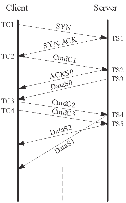
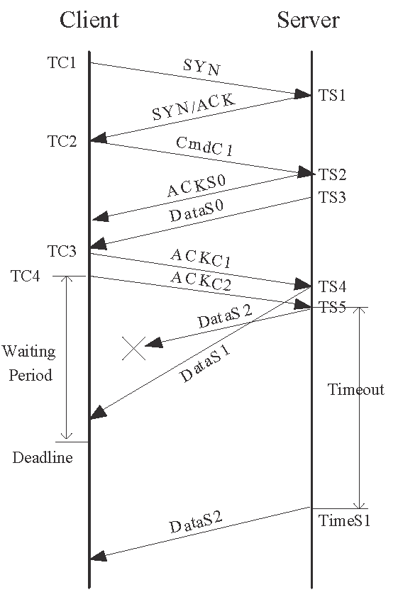
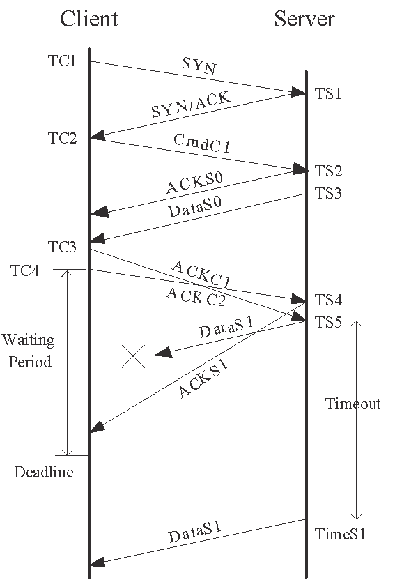
To illustrate the problem, consider the scenario in Fig. 4(a)
where there is backward-path reordering and the segment ![]() is lost. If the client interprets the segment
is lost. If the client interprets the segment ![]() and the retransmitted segment
and the retransmitted segment ![]() as the server's responses to its probing messages, it will arrive
at a false conclusion that there is no packet reordering.
as the server's responses to its probing messages, it will arrive
at a false conclusion that there is no packet reordering.
To remedy this problem, we impose a deadline for receiving responses from
the server. As illustrated in Fig. 4(a), after
the client sends ![]() , it will not accept any response arriving after the deadline and
declare the measurement unsuccessful. In another example, Fig. 4(b)
depicts that the dual-path reordering would be mistaken for the forward-path
reordering if the deadline mechanism were not used. It is obvious that the server
can only use the timeout mechanism to retransmit the lost packet because it
is impossible to trigger the fast retransmit mechanism. We therefore set the
deadline to
, it will not accept any response arriving after the deadline and
declare the measurement unsuccessful. In another example, Fig. 4(b)
depicts that the dual-path reordering would be mistaken for the forward-path
reordering if the deadline mechanism were not used. It is obvious that the server
can only use the timeout mechanism to retransmit the lost packet because it
is impossible to trigger the fast retransmit mechanism. We therefore set the
deadline to
![]() , where
, where
![]() is the mean value of RTT between the client and the
server.
is the mean value of RTT between the client and the
server.
 |
 |
|
| (a) A packet loss in the presence of backward-path reordering | (b) A packet loss in the presence of dual-path reordering |
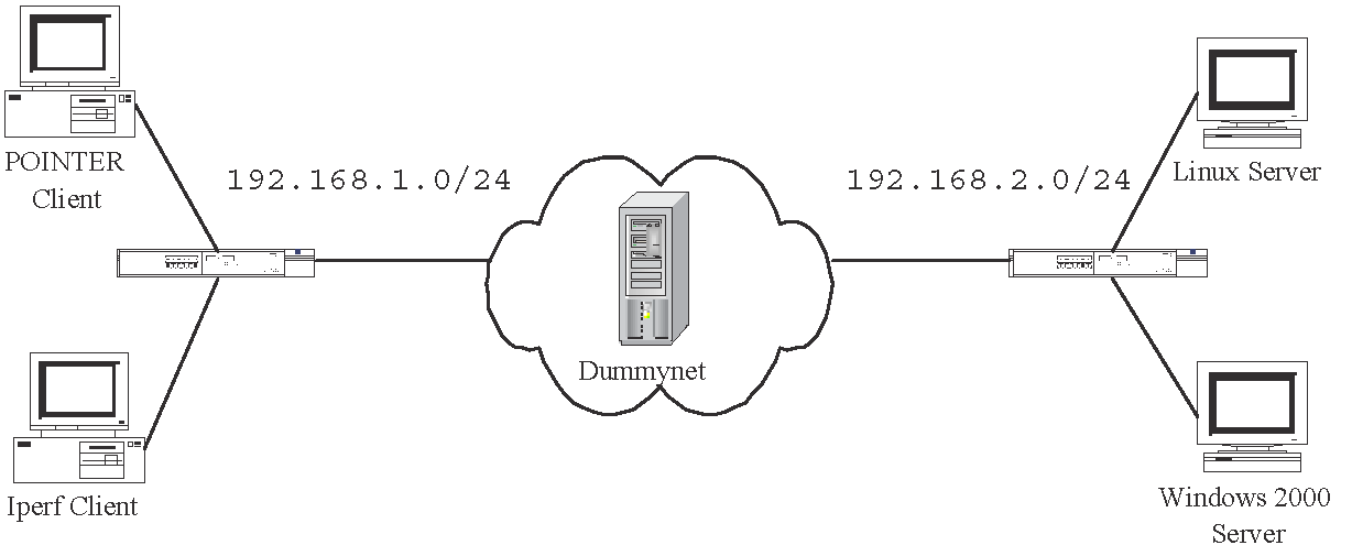
By setting 20 pipes between the subset of 192.168.1.0/24 and 192.168.2.0/24
in the Dummynet, we can emulate the four packet reordering scenarios on the
test-bed. We let each method keep on probing the server until it has detected
![]() packet reordering events in the probing packet pairs. The measurement
results are then compared with the packet traces. Our findings show that all
the detection results produced by the ACM and SAM1 methods are correct for all
test cases. Moreover, we have validated the two methods on other systems available
in our department, including WinXP, Netware, FreeBSD, and Solaris. To validate
the methods with the remaining systems listed in Table 2,
we have conducted the experiments with the WWW servers in the Internet, to be
presented next.
packet reordering events in the probing packet pairs. The measurement
results are then compared with the packet traces. Our findings show that all
the detection results produced by the ACM and SAM1 methods are correct for all
test cases. Moreover, we have validated the two methods on other systems available
in our department, including WinXP, Netware, FreeBSD, and Solaris. To validate
the methods with the remaining systems listed in Table 2,
we have conducted the experiments with the WWW servers in the Internet, to be
presented next.
For each web server, the validation process consists the following steps:
Moreover, we have conducted more measurements from ![]() WWW servers among the 200 websites used in the above validation
process, and obtained
WWW servers among the 200 websites used in the above validation
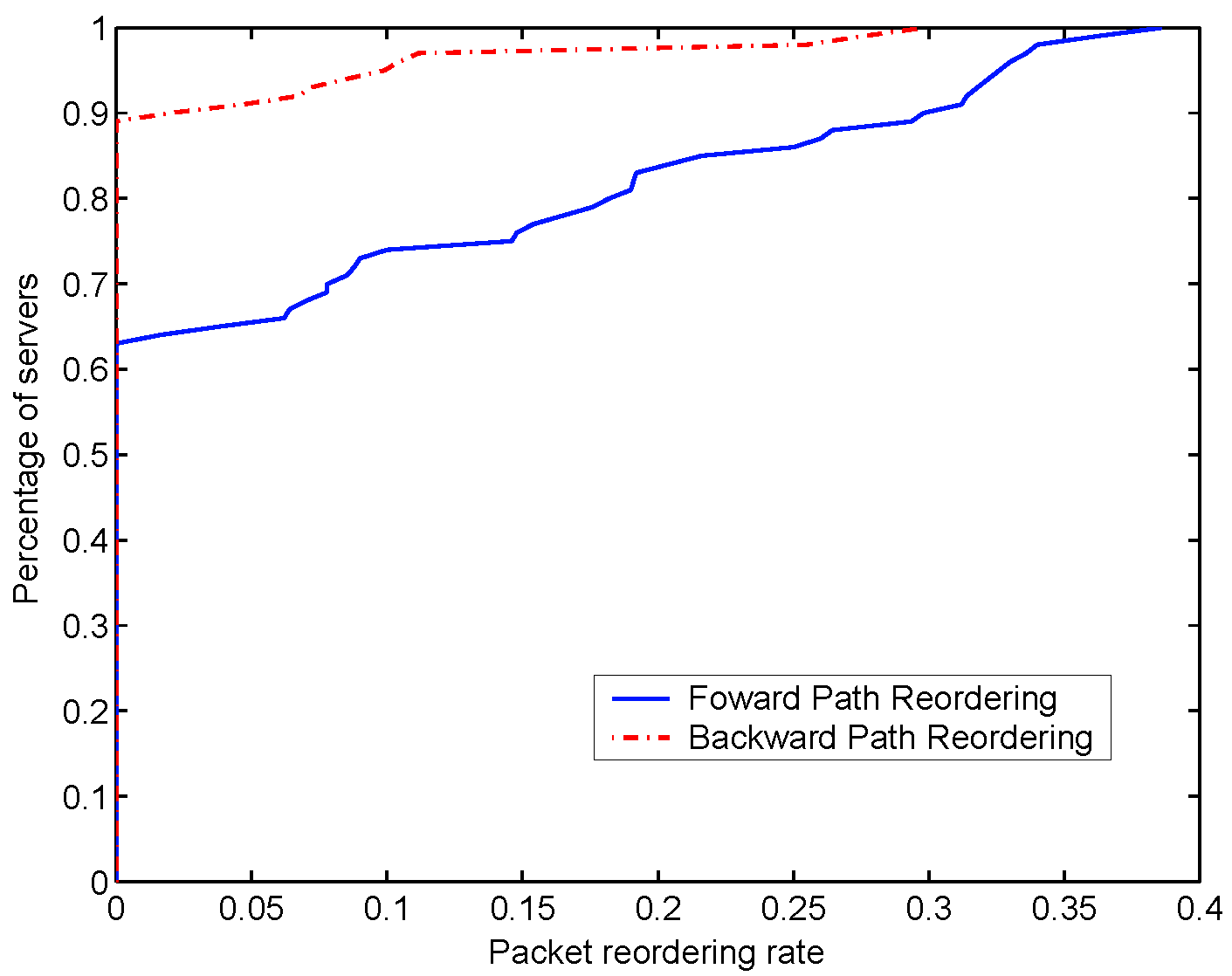
process, and obtained ![]() measurement results for each server. Fig. 6
shows the empirical cumulative distribution function (CDF) of the forward-path
reordering rate and backward-path reordering rate. The measured dual-path reordering
rate is zero for all cases. The rate is given by the percentage of measurements
that indicate the presence of packet reordering. Then we rank all the servers
according to a nondecreasing order of their reordering rates, and obtain the
CDF. The results show that more than
measurement results for each server. Fig. 6
shows the empirical cumulative distribution function (CDF) of the forward-path
reordering rate and backward-path reordering rate. The measured dual-path reordering
rate is zero for all cases. The rate is given by the percentage of measurements
that indicate the presence of packet reordering. Then we rank all the servers
according to a nondecreasing order of their reordering rates, and obtain the
CDF. The results show that more than ![]() of the paths experienced forward-path reordering at least once,
and backward-path reordering was observed on about
of the paths experienced forward-path reordering at least once,
and backward-path reordering was observed on about ![]() of the paths. Moreover, the forward-path reordering was more prevalent
than the backward-path reordering in terms of the percentage of reordering events.
The forward-path reordering rate could go up as high as 0.4, while that for
the backward-reordering was only 0.3.
of the paths. Moreover, the forward-path reordering was more prevalent
than the backward-path reordering in terms of the percentage of reordering events.
The forward-path reordering rate could go up as high as 0.4, while that for
the backward-reordering was only 0.3.
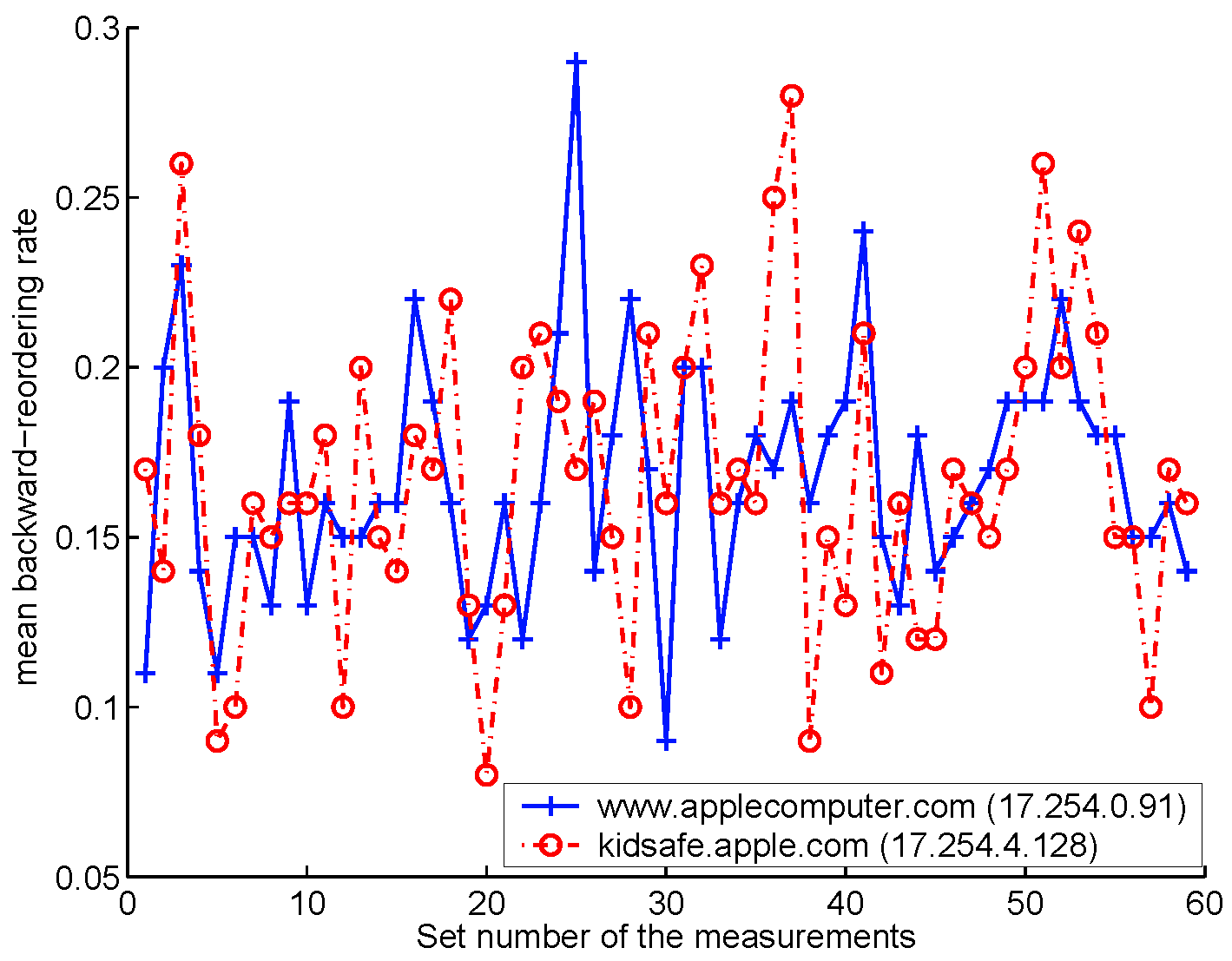
Unlike the previous results for the ![]() websites, the results here indicate that there are more backward-path
reordering events than the forward-path ones. Fig. 7(a)
shows the mean backward-path reordering rates to both servers obtained from
the 59 sets of measurement. Each point is an average of the
websites, the results here indicate that there are more backward-path
reordering events than the forward-path ones. Fig. 7(a)
shows the mean backward-path reordering rates to both servers obtained from
the 59 sets of measurement. Each point is an average of the ![]() samples within a set of measurement. The rates for both servers
are very similar in many sets of samples. Moreover, the overall means rates
for both servers are approximately equal to
samples within a set of measurement. The rates for both servers
are very similar in many sets of samples. Moreover, the overall means rates
for both servers are approximately equal to ![]() . To probe into the issue further, we compute the pair-difference
test statistic for the 59 sets of data [33], and find that with a
. To probe into the issue further, we compute the pair-difference
test statistic for the 59 sets of data [33], and find that with a ![]() confidence interval the backward-path reordering rates are similar
for the two servers.
confidence interval the backward-path reordering rates are similar
for the two servers.
Next, we study and compare the time series of the measurements obtained for the two servers. We use
![]() , to denote the presence/absence of backward-path
reordering in the corresponding sample.
, to denote the presence/absence of backward-path
reordering in the corresponding sample. ![]() refers to www.applecomputer.com and
refers to www.applecomputer.com and ![]() refers to
kidsafe.apple.com.
refers to
kidsafe.apple.com.
![]() in the presence of backward-path reordering; otherwise,
in the presence of backward-path reordering; otherwise,
![]() . We compute the autocorrelation value for the
. We compute the autocorrelation value for the ![]() th set of data according to [34]
th set of data according to [34]
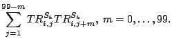 |
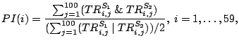
Besides the autocorrelation function, we define a pair-reorder index (PI) by
 |
 |
| (a) The mean backward-path reordering rates. |
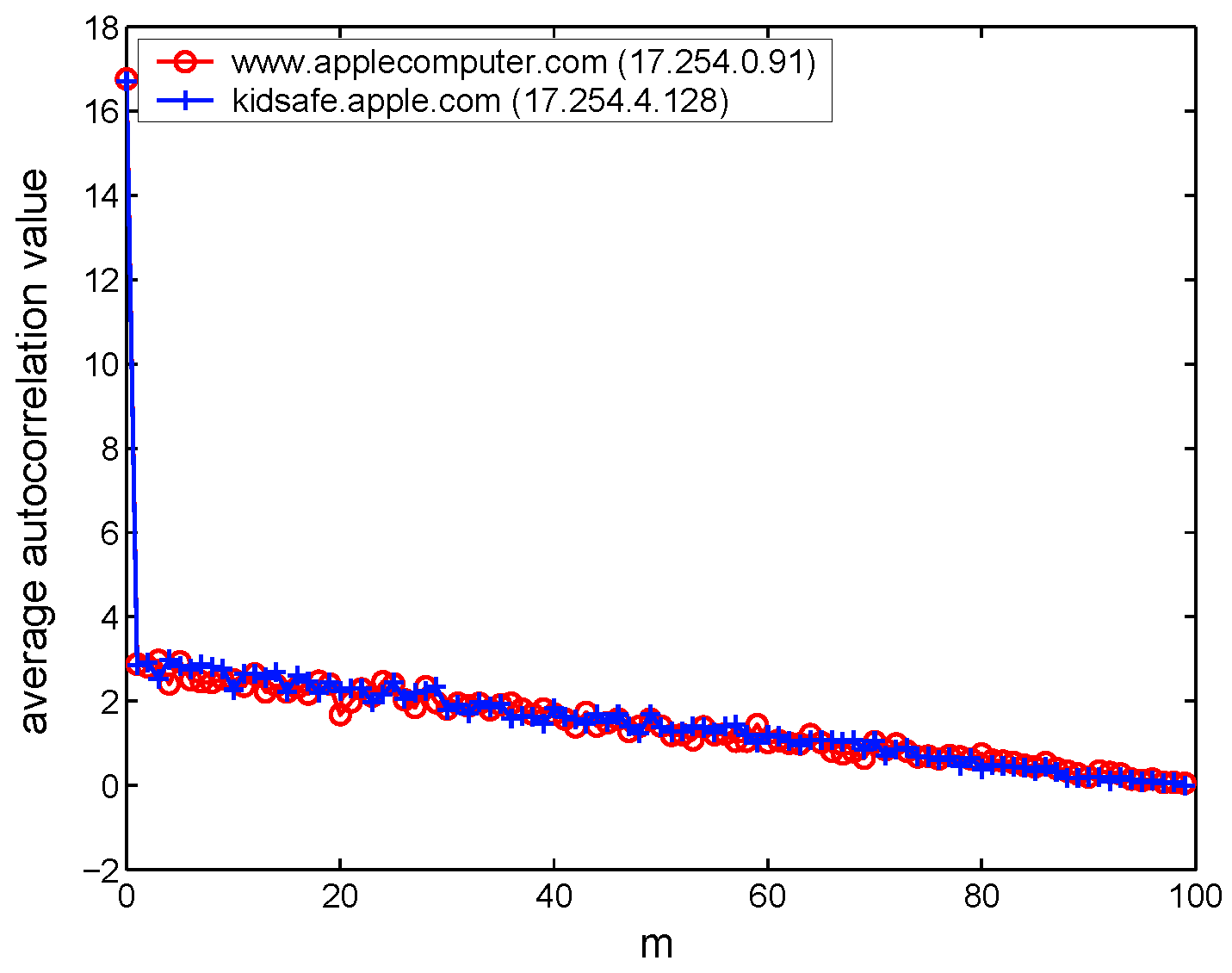 |
| (b) The average autocorrelation of backward-path reordering. |
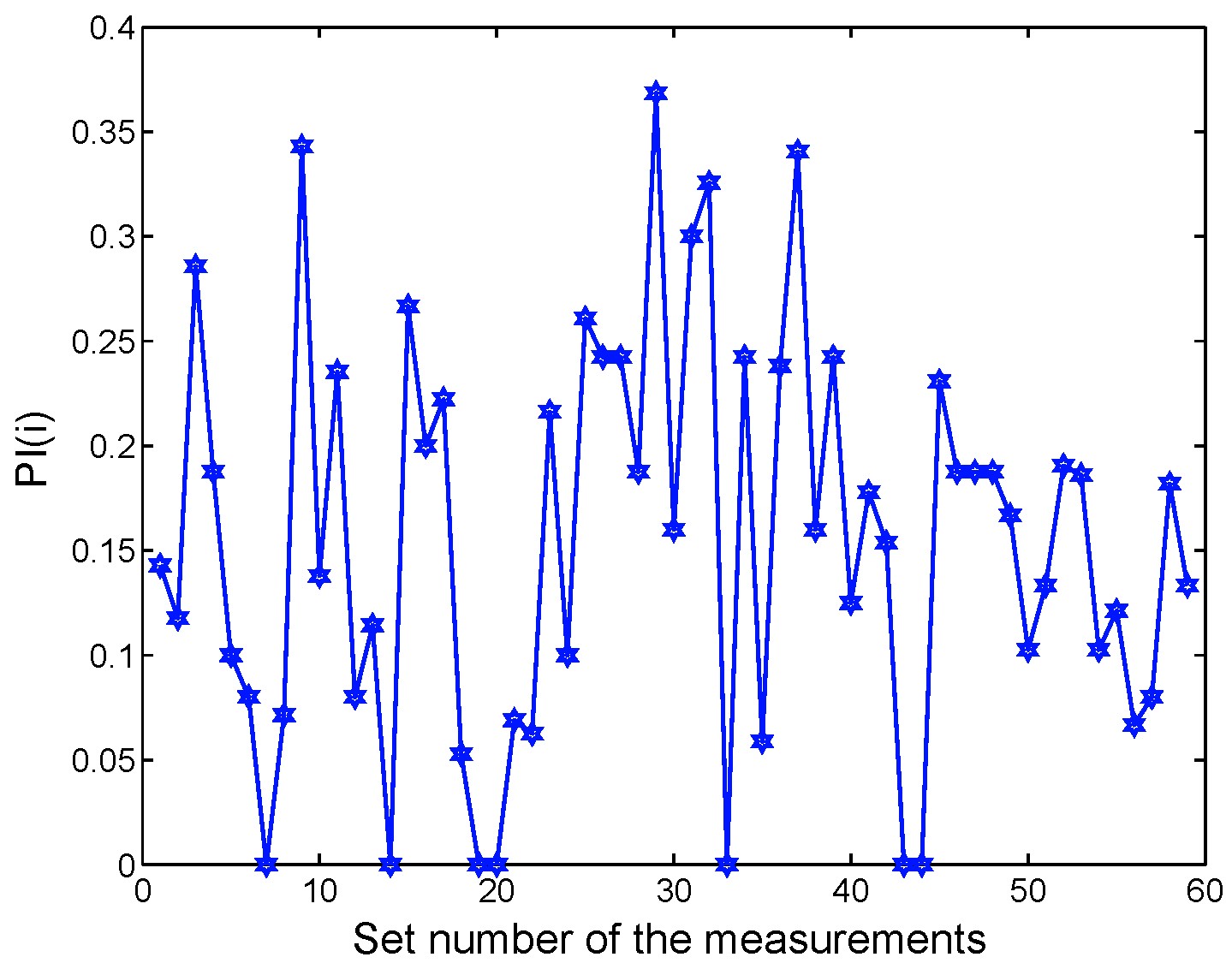 |
| (c) The pair-reorder index for backward-path reordering. |
We have implemented the three methods in POINTER and validated the methods in ![]() most common systems in both a
test-bed and the Internet. We are now in the process of making the tool available in different platforms. With
POINTER, one can detect packet reordering on any path in the Internet. Moreover, the tool can be used to study
other important issues, such as the correlation of packet reordering events presented in this paper.
Furthermore, we are in the process of improving these three methods and conducting a much larger-scale
measurement study on the prevalence of packet reordering in the Internet today.
most common systems in both a
test-bed and the Internet. We are now in the process of making the tool available in different platforms. With
POINTER, one can detect packet reordering on any path in the Internet. Moreover, the tool can be used to study
other important issues, such as the correlation of packet reordering events presented in this paper.
Furthermore, we are in the process of improving these three methods and conducting a much larger-scale
measurement study on the prevalence of packet reordering in the Internet today.
This document was generated using the LaTeX2HTML translator Version 2002-2 (1.70)
Copyright © 1993, 1994, 1995, 1996,
Nikos Drakos,
Computer Based Learning Unit, University of Leeds.
Copyright © 1997, 1998, 1999,
Ross Moore,
Mathematics Department, Macquarie University, Sydney.
|
Last changed: 22 Sept. 2005 aw |