COOTS 1998
[Technical Program]
| Pp. 149–164 of the Proceedings |  |
An Object-Oriented Framework for Distributed Computational Simulation of
Aerospace Propulsion Systems
John A. Reed and Abdollah A. Afjeh
The University of Toledo
Toledo, Ohio
{jreed, aafjeh}@eng.utoledo.edu
Abstract
Designing and developing new aerospace propulsion systems is time-consuming
and expensive. Computational simulation is a promising means for alleviating
this cost, but requires a flexible software simulation system capable of
integrating advanced multidisciplinary and multifidelity analysis methods,
dynamically constructing arbitrary simulation models, and distributing computationally
complex tasks. To address these issues, we have developed Onyx, a Java-based
object-oriented application framework for aerospace propulsion system simulation.
The Onyx framework defines a common component object model which provides
a consistent component interface for the construction of hierarchal object
models. Because Onyx is a framework, component analysis models may be changed
dynamically to adapt simulation behavior as required. A customizable visual
interface provides high-level symbolic control of propulsion system construction
and execution. For computationally-intensive analysis, components may be
distributed across heterogeneous computing architectures and operating systems.
This paper describes the design concepts and object-oriented architecture
of Onyx. As a representative simulation, a set of lumped-parameter gas turbine
engine components are developed and used to simulate a turbojet engine.
1 Introduction
As the aerospace propulsion industry moves into the 21st century, there
is increasing pressure to reduce the time, cost and risk of jet engine development.
To meet the harsh realities of today's marketplace, innovative approaches
to reducing propulsion system design cycle times are needed. An opportunity
exists to reduce design and development costs by replacing some of the large-scale
testing currently required for product development with computational simulations.
Increased use of computational simulations promise not only to reduce the
need for testing, but also to enable the rapid and relatively inexpensive
evaluation of alternative designs earlier in the design process.
As a result of these forces, several government-industry cooperative research
efforts have been established to develop technologies that enable the cost-effective
simulation of a complete air-breathing gas turbine engine. In the United
States, the Numerical Propulsion System Simulation (NPSS) project has been
established between the aerospace industry, Department of Defense, and NASA.
When completed, NPSS will be capable of analyzing the operation of an engine
in sufficient detail to resolve the effects of multidisciplinary processes
and component interactions currently only observable in large-scale tests
[ 1 , 2 ]. For example, more accurate predictions of engine thrust and efficiency
would be possible if the "operational" geometry of a compressor rotor, stator,
and casing could determined based on an analysis of the combined aerodynamic,
structural and thermal loadings [ 3 ].
The topology of such as system is shown in Figure 1. In this system, the
engine component models are integrated to couple relevant disciplines, such
as aerodynamics, structures, heat transfer, combustion, controls and materials.
These models are then integrated at a desired level of fidelity (0-, 1-,
2-, or 3-dimensional) to form coupled subsystems for systems analysis. For
required computing speed at a reasonable cost, simulation models can be
distributed across a networked computing platform consisting of a variety
of architectures and operating systems, including distributed heterogeneous
parallel processors. A simulation environment provides a user-friendly interface
between the analyst and the multitude of complex software packages and computing
systems that form the simulation system.

Figure 1: Topology of Compuational Simulation System
The implementation of such as system is a major challenge. In this paper,
we focus only on the design and development of a prototype simulation environment
being developed in NPSS-related research.
1.1 Design Requirements
This section describes some of the high-level requirements which the gas
turbine simulation environment must meet:
- Component Level Modeling. The primary requirement is for a platform which provides a general and
flexible component view of the engine. Conceptually, this approach allows
an engineer to develop new and different engine simulation models independent
of the number of components in the engine, their type, fidelity level, or
even location in the network.
- Customization. The environment must allow the user to customize simulation functionality
by allowing components to be replaced by other components having different
functionality. Such "pluggability" is essential for keeping the architecture
current. Similarly, it must be capable of supporting the integration of
new simulation techniques and computing methodologies with as little effort
as possible. Specifically, this intended to address the areas of multidisciplinary coupling and multimodeling.
- Component Interoperability. In order for the preceding design requirements to be possible, it is essential
that the user be guaranteed compatibility between all components used to
develop simulation models. Component interoperability is enforced through
specifications of a general component model.
- Distributed Connection and Data Transformation. The introduction of interdisciplinary models and multimodels requires support
for distributed computing as it cannot be assumed that the higher-fidelity
software will run efficiently (or at all) on the same computer platform
as the rest of the system. Additionally, data transferred between components
having different fidelity levels and/or data formats must be transformed
accordingly.
- Portability. The environment must be capable of operating without regard to hardware
or operating system combinations. This includes the ability to leverage
extensive amounts of Fortran, C and C++ legacy software.
- User Interface. Finally, the system must provide a user interface to reduce the efforts
of developing new models and executing simulations.
1.2 Alternatives
A great number of engine simulation software packages are currently in use.
Most of these are proprietary software, developed and maintained by aerospace
companies. Also a number of public domain software packages, developed by
NASA and Universities are also in use [4 , 5 ]. One approach is to determine the "best" software and modify it to address
the design requirements listed above. However, it has been ours and others
experience that this approach often requires more effort and produces less
desirable results than a completely new design [ 6 , 7 ]. Generally, this is due to the following [ 8 ]:
- Procedural design structures. Existing (public domain) simulation software tend to utilize global data
structures, such as FORTRAN common blocks, to improve simulation execution
times. However, the result is a lack of data encapsulation and safety, making
changes in design difficult and dangerous.
- Discipline isolation. Most present-day simulation models offer only simplified coupling of interactions
between, for instance, aerodynamics, structures and controls. Consequently,
the design of the system reflect the bias towards these disciplines. This
makes it difficult to introduce new models to couple additional disciplines.
- Assumed single processor/machine environment. Most simulation systems were designed not to exceed perceived implementation
limitations (hardware, operating systems, memory, etc.). As a result, the
software's design impedes transport to modern parallel and distributed computing
platforms.
- No Graphical Interface. Another drawback of most presently used simulation software is the lack
of graphical user interfaces (GUIs). Engine models are developed by hand
through input lists. This is often a tedious process which can also result
in erroneous model definition.
An alternative approach which directly addresses the first limitation, and
indirectly addresses the remaining limitations is to apply object-oriented technology to the development of the simulation environment. Object-oriented technology
is a collection of powerful design, analysis and programming methodologies
for creating general-purpose adaptive models and robust, flexible software
systems [ 9 , 10 ].
An object-oriented (OO) approach is attractive for modeling gas turbine
systems due to the natural one-to-one correspondence between objects in
the application and computational domains. Consequently, multifidelity and
multidisciplinary representations of engine components can be conveniently
encapsulated through the use of objects. Object class morphology provides
the necessary structure to accommodate a common engineering model, and to
define the essential interfaces for component and disciplinary coupling.
Inheritance of methods and variables in the hierarchy of classes allows
extension and customization of simulation models with an economy of effort.
Moreover, the same structure can be used in the design, analysis, simulation
and maintenance phases of the engineering cycle.
Several prototyping efforts to develop object-oriented gas turbine simulation
systems have already been completed. The first was developed by Holt and
Phillips [ 11 ]. In this work an object-oriented simulator was developed in Common Lisp
Object System (CLOS) with component models based on the dynamic engine software
package called DIGTEM [ 4 ]. Similar prototyping efforts were carried out by Curlett and Felder [ 6 ] and Reed and Afjeh [ 12 ] in C++ and Java` programming languages, respectively. Results from these
efforts were very encouraging. In particular, the use of a graphical user
interface in both the CLOS and Java simulation software greatly increased
flexibility in developing engine simulation models.
1.3 Solution to Design Challenge
These prototyping efforts have illustrated the flexibility and reusability
of the object-oriented approach. However, this has been achieved mainly
at the application level. In order to develop a next-generation simulation
environment, we need to apply OO design concepts to the entire architecture.
In recent years, two complementary concepts, design patterns and OO application frameworks, have been shown to be beneficial to developing reusable and flexible domain-specific
software systems.
A framework is a reusable, "semi-complete" application that can be specialized
to produce custom applications [ 13 ]. In general, the gas turbine simulation software now used are estimated
to be ~80% identical, with the remaining percentage due to proprietary modifications
of individual components. The great amount of commonality suggests that
it might be possible to develop a generalized simulation software package
based on the 80% of common features, and allowing the end user to customize
the remaining 20% as desired. Frameworks can provide the necessary infrastructure
to develop and mange such a generalized propulsion simulation system.
The benefits of object-oriented frameworks are due to their modularity,
reusability, and extensibility. Frameworks enhance modularity by encapsulating
volatile implementation details behind stable interfaces, thus localizing
the impact of design and implementation changes [ 14 ]. These interfaces facilitate the structuring of complex systems into
manageable software pieces æ object-based components æ which can be developed
and combined dynamically to build simulation applications or composite components.
Coupled with graphical environments, they permit visual manipulation for
rapid assembly or modification of simulation models with minimal effort.
Software component modularity also permits placement across computer platforms,
making them well-suited for developing distributed simulations. Reuse of
framework components can yield substantial improvements in model development
and interoperability, as well as quality and performance of the computational
simulation system. Frameworks enhance extensibility by providing "hooks"
into the framework. Coupled with the stable interfaces, these hooks allow
the engineer to "plug" new functionality into the framework as desired.
This is essential for keeping the simulation architecture current and facilitating
new analytical approaches.
In the next section, we describe the design and implementation of Onyx, an object-oriented framework for aerospace propulsion simulation.
2 Overview of Onyx Framework
Onyx is structured as a framework of frameworks. Figure 2 illustrates the
major structural frameworks and components which are described in this paper.
- Engine Component Framework - A database containing collections of domain-specific component models,
such as a compressor and turbines, for use within the Visual Assembly Framework.
- Visual Assembly Framework - The Onyx graphical user interface (GUI) provides interactive control
over the execution of the framework. The Visual Assembly Framework forms
one part of the Onyx GUI and provides tools to visually assemble and manipulate
a simulation model.
- Connector Framework - Provides a layered abstraction mechanism for distributed interconnection
services between component models. Connectors also are utilized in interdisciplinary
and multilevel component connections.
Onyx was developed using the Java object-oriented programming language and
run-time platform [ 15 ]. Java was chosen for the Onyx framework because of its excellent object-oriented
programming capabilities; platform-independent code execution (made possible
through the use of byte-codes and a Java Virtual Machine); free availability
on all major computing platforms; and, highly-integrated run-time class
libraries, which serve as the foundation for Onyx's graphical user interface,
distributed computing architecture, as well as providing future implementation
of database and native code interfacing.
To illustrate how Onyx can be used to develop gas turbine simulations, we
will present a running example throughout this section. A transient, lumped-parameter,
aero-thermodynamic turbojet engine component model, developed in our previous
research, is integrated within the framework. The resulting simulation system
is capable of performing steady-state and transient analyses of arbitrarily
configured jet engine models.

Figure 2: Onyx Framework Layers
3 Engine Component Framework
3.1 Design Challenges
A gas turbine engine is essentially an assembly of engine components -- inlet, fan, compressors, combustor, turbine, shafts and nozzle, etc.
(see Figure 3a). These components operate together to produce power (or
thrust). Engine components are themselves made up of other substructures.
For example, a fan component may be expressed as a collection of hub, stage,
casing, splitter and flowfield substructures (see Figure 3b). These in turn
may be further decomposed into more basic elements such as rotor and stator
blades.
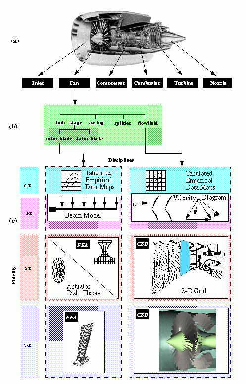
Figure 3: Engine Component Abstraction Diagram
Onyx's Engine Component Framework should allow users to simulate these structures
at the various levels of abstraction as desired. For example, a user should
be able to construct an engine component model from more basic models, and
then use that component model to build an engine model. Such an approach
makes the process of developing gas turbine simulation models both simple
and intuitive. To achieve this, we have selected an internal class structure
which closely resembles the physical structure of the domain.
The component models internal structure should:
- maintain a component models physical relationship. This includes arrangement
of any substructures as well as references to connected component models.
- provide control over the execution of the components simulation algorithm,
which we call, its analysis model.
In developing the component model structure, we should not have to distinguish
between single elements and assemblies of elements in our internal representation.
For example, we should be able to treat a single rotor blade in the same
manner as a fan component comprised of several elements, thus allowing the
construction of arbitrarily complex models.
We can represent the hierarchal structure of the engine, its components,
and substructures using recursive composition. This techniques allows us to build increasing complex elements out of
simpler ones. Returning to Figure 3b, we can combine multiple sets of rotor
and stator blades to form a fan component. The fan component can then be
combined with other component-level elements (compressor, combustor, etc.)
to form an engine model.
3.2 Engine Component Implementation
Figure 4 illustrates the structure of the Engine Components Framework in
Onyx. For simplicity, only the more important variables and methods in the
classes are shown. The structure of these classes is based mainly on the Composite design pattern [ 16 ]. This pattern effectively captures the part-whole hierarchal structure
of our component models.
EngElement is a Java interface which establishes the common behavior for
all engine component classes incorporated into Onyx. It defines the basic
methods needed to initialize, run and stop engine element execution, as
well as methods for managing Port objects. The abstract class DefaultEngElement
implements EngElement and provides default functionality for the interface
methods. In most cases, users will subclass DefaultEngElement to create
concrete engine component classes, such as class XyzEngElement, to implement
the required functional methods. The approach of providing a default abstract
class for a Java interface is used throughout the Onyx system to give the
user more flexibility when plugging in new classes. In this case, the user
may select to inherit the functionality provided by DefaultEngElement, or
to inherit from another class and implement the methods defined by the EngElement
interface.
CompositeEngElement represents a composition of EngElement objects. Management
operations for children are declared in DefaultEngElement to maximize component
transparency. To ensure type-safety, these methods throw an exception for
illegal operations, such as attempting to add or remove an EngElement from
another EngElement, rather than a CompositeEngElement.
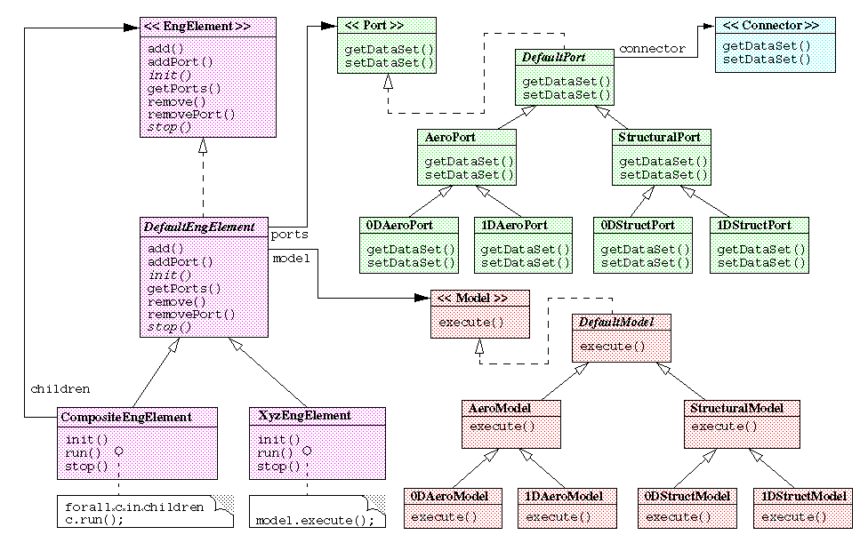
Figure 4: Structure of Engine Component Framework
3.3 Analysis Model Implementation
Computational simulation involves designing a model of an actual or theoretical
physical system, executing the model on digital computer, and analyzing
the execution output [ 17 ]. Models are generally developed by defining a given problem domain, reducing
the physical entities and phenomena in that domain to idealized form based
on a desired level of abstraction, and formulating a mathematical model
through the application of conservative laws.
Simulating complex systems requires the development of a hierarchy of models,
or multimodel, which represent the system at differing levels of abstraction [ 18 ]. Selection of a particular model is based on a number of (possibly conflicting)
criteria, including the level of detail needed, the objective of the simulation,
the available knowledge, and given resources. For preliminary gas turbine
engine design, simulation models are often used to determine the thrust,
fuel consumption rates, and range of an engine. These simulations generally
use relatively simple one-dimensional component models to predict performance.
However, in other situations, such as multidisciplinary analysis, higher-order models are needed. For example, to prevent the possibility
of a fan blade rubbing the cowling, an engineer might perform a coupled
aerodynamic, thermal and structural analysis of the blade to determine the
amount of blade bending due to the thermal and aerodynamic loading. Such
an analysis would require several high-fidelity analysis models using fully
three-dimensional, Navier-Stokes computational fluid dynamics (CFD) and
structural Finite Element analysis (FEA) algorithms.
Ideally, one would prefer using three-dimensional analysis for an entire
engine as it provides greater detail of the physical processes occurring
in the system. The computational requirements for such an analysis, however,
far exceed present computer capabilities. Consequently, it is desirable
for an EngElement to be capable of accommodating views having multiple levels
of fidelity and differing disciplines. Figure 3c illustrates the concept
of multiple views for a rotor blade and flowfield objects in a fan component.
The rotor blade is analyzed using various mechanical-structural methods,
while the flowfield is represented by various aero-fluid-dynamic methods.
Based on the simulation criteria, an appropriate analysis model may be selected.
The complexity of the various analysis models suggest that it is desirable
to encapsulate the analysis model, or remove it from the structure of EngElement.
This would protect the modularity of EngElement, allowing new EngElement
classes to be added without regard to the analysis model, and conversely
to add new analysis models without affecting the EngElement class.
We apply the Strategy design pattern [ 16 ] to encapsulate the analysis model in an object. The DefaultModel class
is an abstract class which implements the Model interface. The interface
defines the methods which all Models must support to be integrated within
Onyx. As an example, two analysis models, 0DAeroModel and 1DAeroModel, are
shown as subclasses of AeroModel.
3.4 Ports
Completing the Engine Component Framework structure is the Port class. In
physical terms, a Port represents a control surface through which energy
and mass flow between engine components. In Onyx, Ports define an interface
between EngElements through which data is passed. Port is an abstract class
which defines the default functionality, and maintains a reference to a
Connector. Connectors will be discussed in section 5. Port is subclassed
according to the discipline (e.g. aerodynamic, structural, thermal, etc.),
and these classes are then each subclassed by fidelity (0-D, 1-D, 2-D, 3-D).
Which subclass of Port an EngElement instantiates is determined by the discipline-fidelity
combination of the EngElements analysis model(s). For example, if EngElement
has a single analysis model which is a 0-D, aerodynamic model, then an instance
of EngElement creates two 0DAeroPort objects to handle input and output.
Because the analysis model is dynamic and may be changed at run-time, the
Port objects also must change accordingly. Consequently, we apply the State design pattern [ 16 ] to dynamically create and manage the Ports in an EngElement.
3.5 Example
To illustrate the application of the Onyx framework and the feasibility
of this approach, a small collection of component object classes representing
the inlet, compressor, combustor, turbine, nozzle, bleed-duct connecting-duct,
and shaft, of a jet engine have been developed. An inter-component mixing
volume class was also defined which is used to connect two successive components
as well as define temperature and pressure at component boundaries. These
concrete classes are all subclasses of the abstract DefaultEngElement class
shown in Figure 4.
Each class implements a specific mathematical (analysis) model which describes
its physical operation. In this example, the analysis models are all relatively
simple differential-algebraic equations (DAE) developed from an space-averaged
treatment of the conservative laws of thermo- and fluid dynamics. These
are patterned after the work of Daniele et al., [ 4 ]. A complete description of the models can be found in the work of Reed
[ 7 ]. The analysis model for each component is encapsulated in an appropriate
subclass of DefaultModel, and present specific implementations of the init(), run() and stop() methods which initialize the component and execute its analysis model,
respectively.
Appropriate Port objects are created in each component object depending
on the number and type of connections required. For example, a compressor
class defines two AeroPort objects to pass aero-thermodynamic data to adjoining
components, and a StructuralPort to pass data to a connecting shaft object.
4 Visual Assembly Framework
4.1 Design Challenges
Aerospace engineers often use schematic drawings to represent propulsion
systems and subsystems. It is then natural to represent computational simulations
of such systems using this visual metaphor.
In the previous section, we developed an object-oriented component model
which allows us to dynamically assemble arbitrarily complex engine system
models. We now consider the development of a framework which supports visual
assembly of those component models.
The main requirement of the Visual Assembly Framework is to provide visual
analogs for the component model objects, and support for assembling them.
This has several implications. The first is obvious: we need visual elements
to represent the objects which form Onyx's engine component model. The second,
less obvious requirement, is that the concept of component composition developed
previously must also be supported visually. Finally, the framework must
take care of managing basic graphical functions -- window management, displaying
objects, moving and dragging visual elements, tracking mouse movements,
etc. This reduces the programming burden for engineers using the framework.
In addition to these goals are some constraints. First, the framework should
decouple the visual user interface (UI) objects from their counterparts
in the component framework. Although the visual elements represent the component,
we would like to allow a component's UI to be changed easily, possibly at
run-time.
Second, our implementation should allow the user to override the default
visual representations as much as is practically possible.
We have selected the Java platform in part because of its integrated graphical
support. Java's Abstract Window Toolkit (AWT) is part of the core classes
which are available in every Java Virtual Machine (JVM). The AWT provides
a collection of platform-independent graphical components for building graphical
applications in Java. One drawback of the AWT is that it provides only basic
low-level graphical components. Another drawback is the heavyweight nature
of the AWT, due to implementing graphical objects with the native windowing
system.
We have opted instead to use the Swing component set to implement our graphic
interface [ 19 ]. Swing is a subset of the new Java Foundation Classes (JFC), which is
itself a subclass of the AWT. Therefore, our graphical interface will retain
the same portability made possible with AWT. Swing however, adds more high-level
graphic components, as well as the ability to select from multiple Look-and-Feel
standards. However, this selection raises some immediate implementation
issues.
One attractive feature of Java is its capability to develop applets -- compiled Java programs which can be dynamically downloaded from a Web
server and run locally on the client's machine using a Java-enabled browser.
The ubiquity of Web browsers make implementing Onyx's visual assembly framework
as an applet very attractive.
One drawback of using an applet is the relatively long time needed to implement
new versions of the JVM into web browsers. Currently, the JFC is not implemented
in any browser, meaning that the Swing classes used in Onyx would have to
be downloaded along with the visual assembly framework each time the applet
was accessed.
Another drawback associated with using an applet is its security restrictions
which affect the partitioning of Onyx's structure. Generally, this limits
communications between the applet to only the web server from which it was
downloaded.
Because of these issues, we have designed the visual assembly framework
as a Java application. Applications are similar to stand-alone programs. As the issues of browser-JVM
integration and applet security issues are addressed, we will modify Onyx
to permit the visual assembly framework to be distributed as an applet.
4.2 Visual Assembly Framework Design
A simulation model is constructed by creating SchematicIcon objects and
connecting them to form an engine schematic. A SchematicIcon is composed
of a VEngElement and one or more VPorts. VConnectors are used to "wire"
the SchematicIcons together. Figure 5 illustrates these relationships.
- VEngElement is the visual analog of the EngElement class in the component
framework. VEngElement is a subclass of
java.swing.JButton, and thus contains an Icon which presents an image of the engine component;
a Label which displays the name of the EngElement object instance.
- One or more VPorts are attached to the VEngElement, and represent connection
points between components. VPorts are color-coded to represent the type
of Port it represents.
- A VConnector is the visual analog of the Connector object. It is represented
as a line drawn between two VPorts.
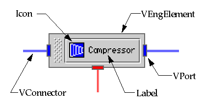
Figure 5: SchematicIcon
Each VEngElement, VPort and VConnector has a popup menu associated with
it. The menu allows the user to access various functions such as moving,
deleting, copying, etc. In the VEngElement, the popup menu has a special
item for "customizing" the component. When selected, the customizer object
is displayed.
Customizers are graphical interfaces which allow the user to change an EngElement's
attributes. Typically, these are used to modify data in the EngElement analysis
model. They may also be used to control the distribution of the EngElement
in a distributed simulation.
In designing the structure for our visual assembly we immediately recognize
from Figure 5 that each instance of SchematicIcon represented in the framework
will likely have different Icons, display names and VPorts. One solution
is to define SchematicIcon as an abstract class, and use inheritance to
define subclasses which represents visually the various concrete SchematicIcon
classes. Each class would then redefine the Icon image, display name, and
VPort location and type. This approach however, typically leads to a very
broad and shallow inheritance tree, indicating little use of inheritance.
A more useful approach would be to create an appropriate SchematicIcon using
object composition. This is accomplished through the use of the parameterized Factory design pattern [ 16 ], in conjunction with Java's reflection mechanism. This also allows us
to address one of the design constraints listed previously: decoupling a
component's UI from its component model representation. Our solution is
to apply a variation of the JavaBeans` "Info" class concept [ 20 ].
We will illustrate this approach by creating a SchematicIcon object for
an XyzEngElement object (see Figure 6). When a user creates an instance
of XyzEngElement (this process will be discussed later), the Visual Assembly
Framework invokes the SchematicIconFactory's create() method. This method invokes the getEngElemInfo() method in the XyzEngElement object which returns the info class name, XyzEngElementInfo.class. The Factory instantiates this class using the java.lang.reflect.Constructor newInstance() method. XyzEngElementInfo implements the EngElementInfo interface which
defines two methods to create and return instances of PortDescriptor and
EngElementDescriptor. We create and return instances of these classes instead
of simply returning the class name, since XyzEngElementInfo initializes
these instances by passing parameters in the constructor of each class.
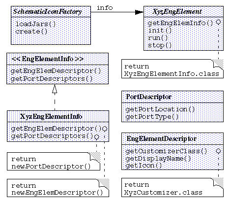
Figure 6: SchematicIcon creation process
PortDescriptor encapsulates information concerning the type, initial placement,
and constraints of the VPorts for XyzEngElement. EngElementDescriptor defines
methods which return the Icon image and display name String used in the
VEngElement button. The method getCustomizerClass() returns the class name for the XyzEngElement's Customizer. This class name
is stored in the VEngElement object, and is lazily initialized using the newInstance() method.
The combination of the Factory pattern and Java reflection gives considerable freedom and flexibility
in creating SchematicIcons. The composition of a SchematicIcon can easily
be redefined by subclassing SchematicIconFactory. We can also use Java reflection
to alter the specific classes that get instantiated in order to build the
SchematicIcon without subclassing. Furthermore, we have effectively separated
the UI implementation from component implementation. One drawback to this
approach is the level of indirection introduced. However, the user sees
little of this complexity as he or she is only required to define the XyzEngElement,
XyzEngElementInfo and a Customizer class.
4.2.1 Customizers
We face another dilemma in creating customizers for each EngElement. Customizer
represents a UI for defining and editing the attributes of an EngElement's
analysis model. Because it is strongly coupled to the data structure for
each specific type of EngElement, we will likely end up with many different
Customizer classes. These may or may not have any commonality, so we may
not be able to take advantage of inheritance. In order to be flexible, Onyx
must be capable of integrating each of these specific Customizers. Furthermore,
we would like to allow users as much flexibility as is possible to customize
the data UI, so we do not want to limit their options through inheritance.
Our solution is to provide an interface which defines a plug-point for user-defined customizers. Figure 7 shows the Customizer structure.
To maximize flexibility, the Visual Assembly Framework allows the user to
1) program a new customizer, or 2) to use the BasicTabbedCustomizer. A user-defined
customizer would inherit from java.awt.Component and implement the Customizer interface methods directly. The commitChanges() and setTarget() methods are called from the Visual Assembly Framework. The constraint of
inheriting from Component is necessary as all customizers are automatically added to an instance
of VCustomizerDialog which expects its child to be a subclass of Component . VCustomizerDialog wraps the Customizer and provides a set of buttons
to accept user input. The setTarget() method identifies the object to be updated, while the commitChanges() method is used to update the object when the user accepts changes to the
customizer data. XyzCustomizer is an example of a user-defined customizer.
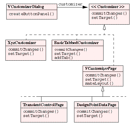
Figure 7: Customizer structure
In the second approach, the user can subclass VCustomizerPage, compose it
with the desired UI objects, and add it to BasicTabbedCustomizer. VCustomizerPage
can provide methods to handle common issues such as laying out components.
Since BasicTabbedCustomizer adds instances of Customizer, it is also possible
to add classes which inherit from java.awt.Component and implement Customizer. Figure 8 shows a picture of an instance of DefaultTabbedCustomizer,
including several VCustomizerPage page objects.
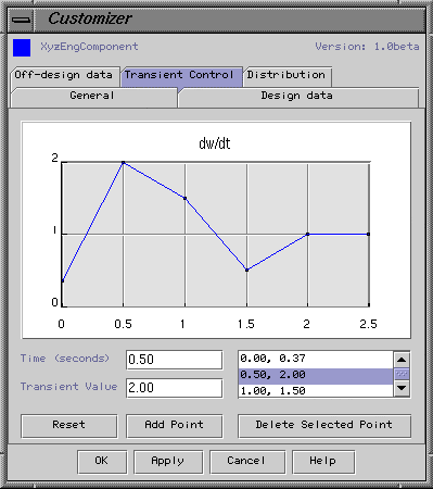
Figure 8: Onyx Customizer
The Customizer structure provides considerable flexibility. It allows the
user select to compose the UI or inherit functionality and structure when
developing a customizer. By adhering to an interface, users can develop
different customizers and plug them in as desired. This process is made
relatively easy with a simple change to the class name returned by the getCustomizerClass() method in EngElementDescriptor. Furthermore, since the VCustomizerDialog
accepts subclasses of java.awt.Component, users can use Java Integrated Development Environments (IDEs) to quickly
construct customizers from AWT or Swing Java Bean GUI components.
4.2.2 Frames, Panes, Managers and SchematicIcons
Engine schematics are built by adding SchematicIcons to a EngSchematicPane
which is contained in a SchematicFrame. EngSchematicPane is a subclass of java.swing.JLayeredPane, and maintains a listing of the SchematicIcons it contains, as well as
their z-order (i.e., their layer). EngSchematicPane also keeps a reference
to an EngSchematicManager, which provides support for selecting and moving
SchematicIcons within the EngSchematicPane (see Figure 9).
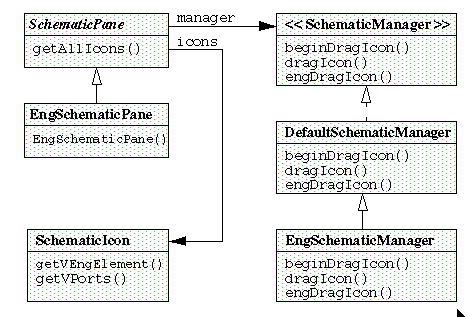
Figure 9: Customizer structure
The SchematicFrame and related classes provide required support for user
interactions: dragging, moving, etc. We also support in the visual framework,
the hierarchal composition concept introduced in the component framework.
In our requirements for a visual assembly framework, we indicated our desire
to support visually the composition of EngElements in the Engine Component
Framework. This is implemented using the SchematicFrame, EngSchematicPane
and SchematicIcons classes. We illustrate it with an example (see Figure
10).
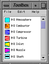 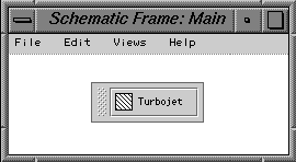
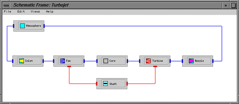
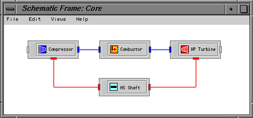
Figure 10: SchematicFrames showing visual composition
4.3 Example
In section 3.5, the EngElement classes representing engine components found
in a turbojet engine were developed. We now demonstrate using the classes
in the Visual Assembly Framework to create a simple turbojet engine. For
each EngElement class, the user also defines an EngElementInfo class with
appropriate descriptor information; including the icon, display name, customizer,
and VPort locations. The customizer, EngElementInfo, and EngElement model
and port classes for each EngElement are then collected into a Java archive
(jar) file.
When the Visual Assembly Framework is started, Onyx searches the default
loading directory, and loads the classes for each of the jar files. The
EngElement classes are extracted and stored for instantiation by a factory
object. The EngElementInfo classes are also extracted and used to obtain
the display names and icons for each of the loaded EngElements. The icons
and display names are listed in the Visual Assembly Toolbox which is displayed
alongside the initial SchematicFrame, called Main (see Figure 10) . From the Main window, the user selects the Create Composite menu command, which creates a new SchematicFrame and places a Composite
SchematicIcon in the Main window. This SchematicIcon represents the top-level
view of the turbojet engine, and the user names it Turbojet. This also sets the title name of the new SchematicFrame to Turbojet.
Next, the user begins to construct the turbojet engine model. From the Toolbox,
the user selects an Inlet, Fan, Shaft, Turbine and Nozzle engine component to add to the Main SchematicFrame. This action creates an proper SchematicIcon for the each component and displays them in the EngSchematicPane. At the same time, Onyx instantiates
their respective EngElements and adds them to an instance of CompositeEngElement
in the Engine Component Framework. Our user next selects the Main SchematicFrame, and using the Create Composite command, instantiates a second SchematicFrame, which the user names Core.
From the Toolbox, the user now selects Compressor, Combustor, Shaft and Turbine components to add to the Core. SchematicIcons for these components are created and displayed in the Core EngSchematicPane. Onyx instantiates their respective EngElements and adds
them to a second instance of CompositeEngElement in the Engine Component
Framework. At this time, a SchematicIcon representing the Core SchematicFrame is added to the Main EngSchematicPane.
We now have two loosely coupled composite hierarchal structures: one composed
of EngElements within CompositeEngElements in the Engine Component Framework;
and its corresponding visual representation composed of SchematicIcons within
EngSchematicPanes. Also notice, from Figure 10, that the relationships between
SchematicIcons, VPorts and VConnectors are maintained in both the Main and Core frames.
5 Connector Framework
5.1 Design Challenges
We have developed a component model for gas turbine components, as well
as a compatible interface so that they can be assembled -- both programmatically
and visually -- to form more complex systems of objects. In order for these
components to interact and simulate the given system, they need to communicate.
In the Onyx architecture, EngElements communicate by sending messages via
a Port.
Consider a physical connection between a Inlet and Fan EngElements as shown in Figure 10. Inlet and Fan are physically and logically
connected and exchange messages, such as getDataSet(), to retrieve data in order to update their analysis models. Normally, this
process would be relatively straightforward, with the getDataSet() request being forwarded from the Fan via the Fan's Port to the Inlet's
Port, and finally to the Inlet, where the request is carried out. In the
Onyx architecture, however, this process is made more complicated by at
least two situations.
5.1.1 Multifidelity Connections
The first situation occurs when two EngElements are connected which have
analysis models with different discipline and/or fidelity combinations.
If, for example, the Inlet component has a 1-D Fluid model and the Fan has
a 2-D Fluid model, then we have a mismatch in fidelity. When the Fan processes
the getDataSet() message, it would have some intelligence capable of transforming
its 2-D data into a 1-D data set before returning it to the Inlet. Other
methods are also needed to perform additional transformations (2-D to 0-D,
2-D to 3-D, etc.). Such transformation methods are clearly necessary in
order for the Onyx architecture to support interdisciplinary and multifidelity
modeling
Holt and Phillips [ 11 ] introduced the concept of connector objects to provide appropriate methods for "expanding" or "contracting"
the data, and mapping from different discipline domains. Connector objects
are essentially intelligent Command objects, as described by the Command design pattern [ 16 ]. As with the command objects, connectors provide flexibility by decoupling
the collaborating objects, making them easier to reuse. An EngElement no
longer need know the discipline-fidelity of the EngElement to which it is
connected. Figure 11 shows an interaction diagram using connectors.

Figure 11: Interaction Diagram
5.1.2 Distributed Connections
The second problematic situation results from the fact that an EngElement
is to be distributable to other machines. The complex and intensive computational
nature of jet engine simulations require that the framework be capable of
distributing computations on a network of computers. This permits access
to high-performance mainframe or workstation clusters for computationally
intensive tasks and, at the same time, permits user control from the local
computer. Also, this feature allows on-line monitoring of computations and
dynamic allocation of computational resources for optimum performance while
a simulation is in progress.
Although the distribution of objects across a network is a relatively complex
task, our goal is to design Onyx to perform this distribution in a manner
totally consistent with non-distributed simulations. Consequently, the distribution
of components across the network should be as transparent as possible to
the user. No actions, other than selecting a remote machine on which to
run a component, should be required to distribute the component at run-time.
To illustrate the process, we return to our Inlet-Fan example.
In this scenario, the user would like to run the Fan component on a remote
machine. In the Visual Assembly Framework, the user creates an Inlet and
Fan. Accessing the Fan's customizer (see Figure 8), the user selects the
"Distribution" page and selects from the list, the name of the remote machine
on which to run the Fan. Now, the user (implicitly) creates a Connector
by drawing a connecting line between the Inlet and Fan Ports. Notice, that
with the exception of selecting the name of the remote machine, the process
is exactly the same as connecting components which run on the same machine.
Placing a component object on the remote machine, however, means that the
two components reside in different Java Virtual Machines. This raises a
difficulty since a Connector has two variables, port1 and port2, which keep references to the Port objects connected to the Connector.
One of these variables would normally be referencing the Fan, but since
it is in a different virtual machine, it cannot be referenced.
We can address this problem by having the Connector reference a remote proxy, as defined in the Proxy design pattern [ 16 ]. The remote proxy provides a local representation for an object in another
design space.
5.2 Connector Framework Implementation
The Connector Framework structure is shown in Figure 12. The Java interface,
Connector, defines our interface functionality. As with previous interfaces,
we provide an abstract class, DefaultConnector, which implements the interface,
provides default implementation of each method, and defines the variables
port1, port2, and isRemote. LocalConnector inherits all of its functionality
and variables from its superclass. It represents a normal (non-remote) Connector.
References to the port1 and port2 objects are passed into the constructor. RemoteConnector's constructor
takes an additional argument to identify the remote machine. RemoteConnector
defines a proxy variable to hold the reference to the proxy object. The
constructor also initializes Onyx's interconnection service to bind proxy
to the remote object.

Figure 12: Structure of Connector Framework
Onyx's distribution mechanism is currently based on the Java Remote Method
Invocation (RMI), a core component of the Java platform. RMI uses client
stubs and server skeletons to interface with the local and remote objects.
The stub represents the remote proxy object which is referenced by the RemoteConnector
proxy variable
Because RMI is designed to operate fully within the Java environment, it
is limited to connections between machines which are running the Java Virtual
Machine. By assuming the homogeneous environment of the JVM, Onyx can take
advantage of the Java object model whenever possible. This provides a simple
and consistent programming model. Given that most computing platforms now
provide a JVM, this should not limit the use of the framework. However,
we are also in the progress of integrating CORBA for providing non-Java
distributed object support. This is especially important for incorporation
of the multitude of legacy applications not written in Java which currently
exist in the aerospace industry.
Our Connector now provide two sets of functionality: 1) it can transform
data sets between two components of different fidelity, and 2) it establishes
and maintains communications between distributed components. Although both
functions are based on decoupling the connected components, we would prefer
that Connector has a more singular functionality. This would make it more
reusable in the future. To achieve this, we delegate the transformation
responsibility to a separate Transform object. Connector selects an appropriate
Transform object using a State pattern [ 16 ], based on the fidelity-discipline combination of the connection. The
Transform object utilizes the Strategy pattern [ 16 ], to allow different transformation algorithms, such as Fluid1Dto2D, to
be interchangeable.
The Connector makes connections between EngElements transparent. Both distributed
and multifidelity connections can be made without regard to location of
the component, or its fidelity. Modifying the distribution mechanism can
be performed either by subclassing DefaultConnector, or implementing Connector
directly. Also, connection implementation details are fully encapsulated
by the Connector, allowing EngElement and Port to remain unaffected by an
changes to the distribution mechanism.
5.3 Example
For test purposes we have established a simple peer-to-peer distribution
mechanism for the EngElement objects in our example model. EngElement objects
are instantiated on the remote machine and export their interface so that
their init(), run() and stop() methods may be called by Onyx from a local machine. In addition, a RemotePort
interface was defined and is exported to allow connections from local (non-remote)
Port objects. This interface allows the connectors and ports to invoke the getDataSet() methods to return a serialized object containing necessary engine component
operating states.
Future efforts in this area will investigate the use of mobile object technology,
such as ObjectSpace's Voyager [ 21 ], to allow the user to dynamically relocate EngElement objects to other
platforms on the network.
6 Concluding Remarks
Designing and developing new aerospace propulsion technologies is a time-consuming
and expensive process. Computational simulation is a promising means for
alleviating this cost, due to the flexibility it provides for rapid and
relatively inexpensive evaluation of alternative designs, and because it
can be used to integrate multidisciplinary analysis earlier in the design
process [22]. However, integrating advanced computational simulation analysis methods
such as CFD and FEA into a computational simulation software system is a
challenge. A prerequisite for the successful implementation of such a program
is the development of an effective simulation framework for the representation
of engine components, subcomponents and subassemblies. To promote concurrent
engineering, the framework must be capable of housing multiple views of
each component, including those views which may be of different fidelity
or discipline [23]. In addition, the framework must address the challenges of managing this
complex, computationally intensive simulation in a distributed, heterogeneous
computing environment.
Object-oriented application frameworks and design patterns help to enable
the design and development of aerospace simulation systems by leveraging
proven software design to produce a reusable component-based architecture
which can be extended and customized to meet future application requirements.
The Onyx application framework described in this paper provides an ensemble
of framework components which, together, form an integrated framework for
propulsion system simulation. Figure 13 shows how the individual framework
component structures combine to form the Onyx framework.
Onyx promotes the construction of aerospace propulsion systems, such as
jet gas turbine engines, in the following ways. First, it provides a common
engine component object model which: encapsulates the hierarchal nature
of the physical engine model, is capable of housing multimodel and multifidelity
analysis models, and enforces component interoperability through a consistent
interface between components. Second, it enables the construction and of
engine models and customization of the simulation at a high level of abstraction
through the use of visual representation in the visual assembly framework.
Third, it supports both connection and transformation of data between multifidelity
components running in a distributed network environment. Finally, the object-oriented
design, built-in support for graphical interfaces and heterogeneous distributed
processing, and automatic memory management, in Java greatly simplify and
unify the design and development of Onyx. In addition, Java's byte code
and widely available Java Virtual Machine allows Onyx to be highly portable.
The use of object-oriented application framework and design pattern methods
in Onyx help to decouple domain-specific simulation strategies from their
implementations. This decoupling enables new simulation strategies (e.g.,
components, analysis models, solvers, etc.) to be integrated easily into
Onyx. By applying these design strategies, Onyx allows users to dynamically
alter simulation models during any phase of the simulation. The example
presented in the paper serves to illustrate the flexibility, extensibility,
and ease of using Onyx to develop aerospace propulsion system simulations.

Figure 13: Onyx Aerospace Propulsion System Simulation Framework
Acknowledgments
The work described in this paper was made possible by funding from the NASA
Lewis Research Center Computing and Interdisciplinary System Office (Grant
No. NCC-3-207), and the University of Toledo. Mr. Reed is partially supported
by a University of Toledo Doctoral Fellowship. We would like to thank Greg
Follen at NASA Lewis for his continued support. Special thanks also to Murthy
Devarakonda for his guidance in preparing this paper. More information on
Onyx is available at www-mime.eng.utoledo.edu/~jreed/.
References
- Claus, R. W., Evans, A. L., Lytle, J. K., and Nichols, L. D., 1991, "Numerical
Propulsion System Simulation," Computing Systems in Engineering, Vol. 2, pp. 357-364.
- Claus, R. W., Evans, A. L., and Follen, G. J., 1992, "Multidisciplinary
Propulsion Simulation using NPSS," AIAA Paper No. 92-4709
- Evans, A. L., Lytle, J., Follen, G., and Lopez, I., "An Integrated Computing
and Interdisciplinary Systems Approach to Aeropropulsion Simulation," ASME
Paper No. 97-GT-303.
- Daniele, C. J., Krosel, S. M., Szuch, J. R., and Westerkamp, E. J., 1983,
"Digital Computer Program for Generating Dynamic Engine Models (DIGTEM),"
NASA TM-83446.
- Plencer, R., and Snyder, C., 1991, "The Navy/NASA Engine Program (NNEP89)
- A User's Manual," NASA TM-105186.
- Curlett, B. P. and Felder, J. L., 1995, "Object-oriented Approach for Gas
Turbine Engine Simulation," NASA TM-106970.
- Reed, J. A., 1993, "Development of an Interactive Graphical Aircraft Propulsion
System Simulator," MS Thesis, The University of Toledo, Toledo, OH.
- Drummond, C., Follen, G., and Cannon, M., 1994, "Object-Oriented Technology
for Compressor Simulation," AIAA Paper No. 94-3095.
- Taylor, D. A., 1990, "Object-Oriented Technology: A Manager's Guide," Addison
Wesley Publishing Company, Inc., Reading, MA.
- Booch, G, 1991, "Object Oriented Design with Applications," The Benjamin/Cummings
Publishing Company, Inc., New York, NY.
- Holt, G., and Phillips, R., 1991, "Object-Oriented Programming in NPSS Phase
II Report," NASA CR-NAS3-25951.
- Reed, J. A., and Afjeh, A. A., 1997, "A Java-based Interactive Graphical
Gas Turbine Propulsion System Simulator," AIAA Paper No. 97-0233.
- Johnson, R. and Foote, B., 1988, "Designing Reusable Classes," Journal of Object-Oriented Programing, Vol. 1, pp. 22-35.
- Schmidt, D. C., 1997, "Applying Design Patterns and Frameworks to Develop
Object-Oriented Communications Software," Handbook of Programming Languages, Volume I, P. Salus, ed., MacMillian Computer Publishing.
- Arnold, K. and Gosling, J., 1996, "The Java Programming Language," Addison
Wesley Publishing Company, Inc., Reading, MA.
- Gamma, E., Helm, R, Johnson, R., and Vlissides, J., 1995, "Design Patterns:
Elements of Reusable Object-Oriented Software," Addison Wesley Publishing
Company, Inc., Reading, MA.
- Fishwick, P. A., 1997, "Computer Simulation: Growth Through Extension,"
TRANSACTIONS of The SCS, Vol. 14, pp. 13-23.
- Fishwick P. A. and Zeigler, B. P., 1992, "A Multimodel Methodology for Qualitative
Model Engineering," ACM Transactions on Modeling and Computer Simulation, Vol. 12, pp. 52-81.
- Swing, 1997, "The Swing Connection," Available from https://java.sun.com/products/jfc/swingdoc-current/index.html.
- Englander, R., 1997, "Developing Java Beans," O'Reilly & Associates, Inc.,
Sebastopol, CA.
- Voyager, 1998, "ObjectSpace Voyager Core Package Technical Overview," Available
from https://www.objectspace.com/.
- Jameson, A., 1997, "Re-Engineering the Design Process through Computation,"
AIAA Paper No. 97-0641.
- Irani, R. K., Graichen, C. M., Finnigan, P. M., and Sagendorph, F., 1994,
"Object-based Representation for Multidisciplinary Analysis," AIAA Paper
No. 94-3093.
|
